May 04, 2026
Three-view markerless 3D hand-motion protocol
- Hideto Tobishima1,
- Takeshi Saito2,
- Kohei Koizumi2,
- Toyohiro Hamaguchi2
- 1Department of Health Sciences and Welfare Studies, Saitama Prefectural University, Koshigaya, Saitama, Japan;
- 2Saitama Prefectural University, Koshigaya, Saitama, Japan


Protocol Citation: Hideto Tobishima, Takeshi Saito, Kohei Koizumi, Toyohiro Hamaguchi 2026. Three-view markerless 3D hand-motion protocol. protocols.io https://dx.doi.org/10.17504/protocols.io.x54v9qxk1l3e/v1
License: This is an open access protocol distributed under the terms of the Creative Commons Attribution License, which permits unrestricted use, distribution, and reproduction in any medium, provided the original author and source are credited
Protocol status: Working
We use this protocol and it's working
Created: April 29, 2026
Last Modified: May 04, 2026
Protocol Integer ID: 315946
Keywords: stroke rehabilitation, hand kinematics, markerless motion capture, MediaPipe, multi-view 3D reconstruction, reach-and-grasp, test–retest reliability, view markerless 3d hand, markerless 3d hand, hand tracking, limb kinematic assessment, hand landmark model, time hand tracking from rgb image, time hand tracking, mediapipe hands landmark estimator, based hand tracking, markerless 3d reconstruction of reach, kinematic assessment, markerless video, grasp kinematics after stroke, markerless 3d reconstruction, motion protocol synchronized smartphone, grasp kinematic, palm detector, fine finger movement, 2d landmark extraction, capture hardware, tablet camera, mediapipe hand, camera, trial reliability of segment, cameras as the primary reconstruction mode, internal geometric validation, limb, evidence anchor this protocol
Abstract
Synchronized smartphone workflow for markerless 3D reconstruction of reach-and-grasp kinematics after stroke
| Field | Entry | |
| Protocol type | Experimental and computational workflow | |
| Core technique | Three-view video capture, MediaPipe Hands 2D landmark extraction, calibrated DLT triangulation with three-camera primary and two-camera fallback reconstruction, and reliability analysis | |
| Participants | Adults with post-stroke hemiparesis within 6 months of onset, with independent unsupported sitting and capacity to provide informed consent | |
| Main outputs | 2D landmark CSV files, temporal synchronization offsets, unfiltered 3D Raw and Strict datasets, 6 Hz filtered 3D Raw and Strict datasets, reprojection error, anatomical segment CV, valid-frame rate, ICC(2,1), SEM, and MDC95 | |
| Primary code files | calibration.py, video_to_csv.py, time_sync.py, data_integration.py, reprojection.py, anatomical_check.py, single_anatomical_check.py, database.py, icc.py |
Scientific rationale and evidence anchor
This protocol is designed for a PLOS ONE Lab Protocol article. PLOS ONE defines Lab Protocols as two linked components: a step-by-step protocol hosted on protocols.io and a peer-reviewed PLOS ONE article that contextualizes the protocol. PLOS ONE also requires that the article describe the value added by the protocol and provide evidence that the protocol works through a supporting publication or through validation or benchmarking data.
MediaPipe Hands provides a palm detector and a hand landmark model for real-time hand tracking from RGB images. Prior validation studies have shown that markerless video-based hand tracking requires direct validation against established systems, especially for fine finger movement and clinical applications. This protocol therefore combines internal geometric validation, anatomical segment-length stability, monocular comparison, and test-retest reliability instead of relying on a single reprojection-error metric.
Overview
This protocol describes a reproducible workflow for clinical upper-limb kinematic assessment using three consumer smartphone or tablet cameras and the MediaPipe Hands landmark estimator. The workflow covers synchronized multi-view video acquisition, 2D landmark extraction, temporal alignment by ray-distance optimization, 3D reconstruction by Direct Linear Transformation (DLT) using all three cameras as the primary reconstruction mode with a two-camera fallback when one camera transiently fails, and validation by reprojection error, anatomical segment-length consistency, and test-retest reliability. The pipeline requires no optical motion-capture hardware.
Validation considerations
Because the reprojection-error threshold in Step 7 is also a component of the constraint screen, the reprojection error reported in Step 8 characterizes the internal geometric consistency of the selected camera combination rather than independent accuracy. The protocol therefore reports two additional metrics — the 14-segment anatomical segment-length coefficient of variation (Step 9) and the between-trial reliability of segment-level means (Step 12) — that are not part of the Step-7 selection rule.
The 6.0 Hz filter is applied only to Route B for kinematic and reliability analyses. The 2.0 Hz filter is applied only to the unfiltered Route A input for anatomical stability analysis. These filters are never applied sequentially to the same signal.
The millimeter conversion of reprojection error depends on the estimated working distance. The protocol therefore reports −30 % and +30 % working-distance sensitivity bounds alongside the nominal value.
Step–script–input–output mapping
| Step | Script | Primary input | Rrimary output | |
| 2 | calibration.py | Three calibration videos | calibration.npz | |
| 5 | video_to_csv.py | Per-camera task video | Per-camera 2D landmark CSV | |
| 6 | time_sync.py | 3 × 2D CSV, calibration.npz | SYNC_TIME_A/B/C offsets | |
| 7 | data_integration.py | 3 × 2D CSV, SYNC_TIME_A/B/C offsets, calibration.npz | Unfiltered_Raw, Unfiltered_Strict, Raw, Strict, Valid_Frame_Rate.csv | |
| 8 | reprojection.py | Unfiltered_Raw, calibration.npz | Reprojection error table | |
| 9 | anatomical_check.py | Unfiltered_Raw, Unfiltered_Strict | 14-segment CV table | |
| 10 | single_anatomical_check.py | Camera A 2D CSV | Monocular 14-segment CV table | |
| 11 | database.py | 6 Hz filtered Strict datasets | ICC_Database_14Pairs.csv | |
| 12 | icc.py | ICC_Database_14Pairs.csv | ICC (2,1), 95 % CI, SEM, MDC95 table |
Guidelines
Participant inclusion and exclusion criteria
Inclusion criteria
1. Adults with post-stroke hemiparesis after ischemic or hemorrhagic stroke, within 6 months of onset.
2. Independent unsupported sitting on a backless chair.
3. Cognitive comprehension sufficient to understand the study and provide informed consent.
Exclusion criteria
1. Severe cognitive or affective impairment that prevents informed consent.
2. Neurological or musculoskeletal conditions unrelated to stroke that affect upper-limb movement.
Ethics, privacy, and safety
Obtain institutional ethics approval before recruitment and obtain written informed consent from each participant.
Confirm unsupported sitting balance before enrollment. Remove obstacles around the chair and table.
Keep a therapist within arm reach during task performance.
Provide rest intervals between sets. Stop the session immediately when the participant reports pain, dizziness, or discomfort.
Adjust camera height and framing so that the face is excluded from the field of view during task recording.
Label videos and CSV files with anonymized participant IDs, such as L01, and keep the link between IDs and personal identifiers in a separate secured file.
Store raw and derived data on a password-protected analysis workstation isolated from external networks.
Materials
Materials and equipment
| Item | Specification | |
| Cameras | Two smartphones and one tablet, each mounted on a tripod. Example devices: iPhone 14, iPhone SE, and iPad. Equivalent consumer cameras can be used when full-HD 30 fps recording and manual exposure or focus control are available. | |
| Calibration checkerboard | Square size 22 mm × 22 mm, 10 × 7 inner corners. | |
| Chair | Backless chair, seat height 45 cm. | |
| Table | Height 70 cm. | |
| Grasp objects | Cylindrical PET bottle and tennis ball. | |
| Marking supplies | Tape for hand start position and object position. | |
| Analysis computer | macOS workstation or equivalent computer capable of running Python 3.11.x. |
Software and system requirements
| Component | Version or role | |
| Python | 3.11.x | |
| MediaPipe | v0.10.x, hand landmark estimation | |
| OpenCV-Python | v4.x, calibration and image processing | |
| NumPy, pandas, SciPy | Numerical processing, interpolation, and Butterworth filtering | |
| pingouin | v0.5.x, intraclass correlation coefficient computation | |
| Custom Python scripts | Scripts listed in the metadata table and Step-script mapping table |
Troubleshooting
Problem
MediaPipe loses the hand in multiple frames
Solution
Adjust oblique camera angles and increase diffuse illumination. The two-camera fallback in Step 7 will absorb brief single-camera losses, but frequent losses in two or more cameras degrade the valid-frame rate.
Problem
High reprojection error across all landmarks
Solution
Recalibrate with the board moved across the full measurement volume and verify tripod stability.
Problem
Unstable segment lengths
Solution
Re-seat tripods, improve contrast, and repeat practice tracking check.
Problem
Low valid-frame rate during bottle grasp
Solution
Report the valid-frame rate alongside CV and rely on the ABC-primary reconstruction for frames where all three cameras remain valid.
Problem
ICC (2,1) below 0.75 for a segment
Solution
Verify start-position and object-position tape marks, insert longer rest intervals, and confirm that the reliability subset covers a sufficient range of segment-length values.
Problem
Unexpected differences in ICC across runs
Solution
Normalize condition labels to a single case convention in Step 11 before running Step 12.
Before start
- Charge all cameras and confirm storage capacity for at least two 30-minute recordings.
- Prepare the calibration checkerboard with 22 mm squares and 10 × 7 inner corners.
- Confirm diffuse room lighting and remove strong back-lighting or shadows on the hand.
- Remove reflective or occluding objects from the recording field.
- Create a directory structure for participant ID, side, object condition, set number, and camera ID.
- Confirm that the Python environment contains the package versions listed above.
Setup and Calibration
Camera setup and environmental configuration
See Appendix 1.
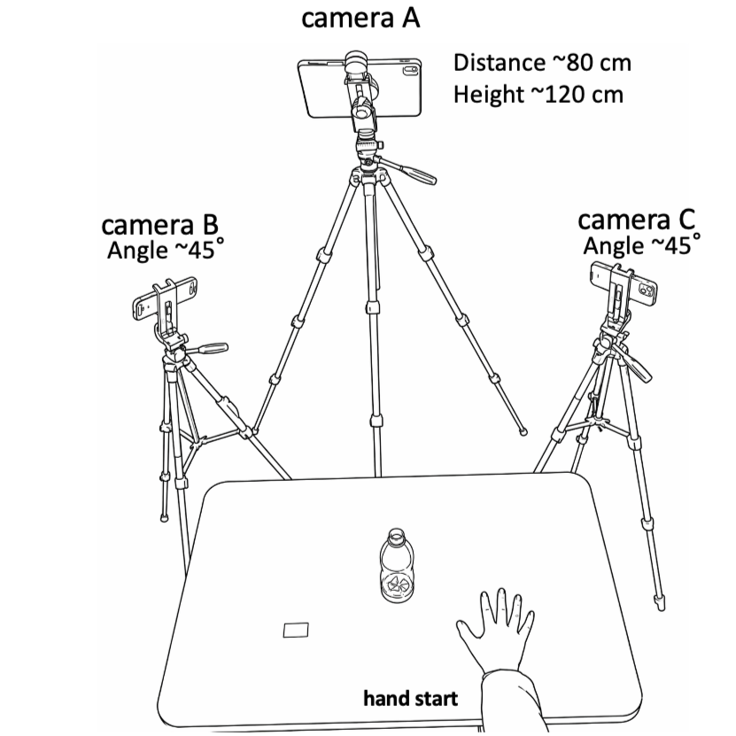
Appendix 1. Three-view camera setup for multi-view recording of reach-and-grasp movements. The participant sat on a chair without a backrest, with the tested hand resting on the tabletop at the marked start position. The target object was placed on the body midline, 30 cm anterior to the participant. Camera A was positioned in front of the participant and aligned with the midsagittal plane. Cameras B and C were positioned at left and right oblique angles of approximately 45 degrees. The cameras were mounted on tripods at an approximate height of 120 cm and placed approximately 80 cm from the center of the tabletop measurement volume. Video was recorded at 1920 x 1080 pixels and 30 frames/s with fixed exposure and fixed focus. A checkerboard with 22 mm squares and 10 x 7 inner corners was used to calibrate the three-camera volume. This triangular camera configuration covered the tabletop movement area used for 3D reconstruction.
Place Camera A frontal to the participant, aligned with the participant midsagittal plane on the opposite side of the table, and frame the full tabletop.
Place Camera B at the left-anterior oblique position, approximately 45 degrees from the frontal view.
Place Camera C at the right-anterior oblique position, approximately 45 degrees from the frontal view.
Set each camera at approximately 120 cm height. Configure all cameras to 1920 × 1080 resolution and 30 fps.
Disable auto-exposure and autofocus when the camera application allows manual control.
Ask the participant to perform a practice reach-and-grasp task. Use a real-time landmark overlay to confirm that all 21 hand landmarks remain trackable in all three views.
Adjust camera angles until the hand is visible from at least two cameras during object contact and lift.
Note
All cameras frame the table, start position, object position, and complete hand movement path. Landmark tracking remains stable during the practice task.
Camera calibration
Script: calibration.py
Start recording on all three cameras.
Move the checkerboard through the measurement volume for at least 30 seconds. Vary board orientation and depth while keeping the board fully visible in all three cameras.
Stop recording and transfer calibration videos to the analysis workstation.
Run the calibration script to estimate intrinsic parameters for each camera by checkerboard detection.
Estimate pairwise extrinsic parameters between Camera A-B and Camera A-C using stereo calibration with fixed intrinsics.
Save intrinsics, distortion coefficients, extrinsics, and inter-camera baseline to a single calibration .npz file.
Note
Calibration.npz is generated and no camera pair has failed checkerboard detection across the calibration volume.
Data Acquisition
Participant preparation
Seat the participant without shoes at the edge of the 45 cm chair in upright unsupported sitting.
Place the table anterior to the participant at 70 cm height.
Set the start upper-limb posture as shoulder neutral, elbow flexed to 90 degrees, forearm pronated, and hand resting on the tabletop.
Mark the hand start position with tape.
Place the target object on the participant midline, 30 cm anterior to the start position.
Mark the object position with tape for each condition.
Note
The hand start position and target-object position are marked and used across all sets.
Task recording and manual synchronization
Two operators start the three cameras on one verbal cue. Perfect simultaneity is not required because the residual offset is corrected computationally.
Instruct the participant: From the start posture, reach forward to the target object, grasp it, lift it, return it to the marked position, and return your hand to the start position.
Allow one practice trial.
Record three consecutive reach-grasp-return cycles as one set.
Record two sets per object condition, bottle and ball, on the affected and unaffected sides.
Stop the cameras on a verbal cue after the hand has returned to the start position at the end of the third cycle.
Save each video with participant ID, side, object condition, set number, and camera ID.
Example: 01_Paretic_bottle_set1_CamA.MOV
Note
Each condition has synchronized video files from Camera A, Camera B, and Camera C with consistent filenames.
Data Processing and 3D ReconstructionUntitled section
2D landmark extraction
Script: video_to_csv.py
Load each camera video in Python.
Process each video frame by frame with MediaPipe Hands.
Extract the 21 hand landmarks for each frame as 2D pixel coordinates and visibility values.
Read frame time from the video presentation timestamp using OpenCV CAP_PROP_POS_MSEC instead of assuming a fixed frame interval.
Save per-camera CSV files containing frame index, timestamp in seconds, 2D x and y pixel coordinates, and visibility for all 21 landmarks.
Note
Each camera produces a 2D landmark CSV with timestamps and 21 landmark coordinate pairs.
Temporal synchronization across cameras
Script: time_sync.py
Load the three 2D landmark CSV files and calibration.npz.
For each candidate temporal offset within the prespecified search window, perform provisional triangulation of landmarks.
Back-project camera rays and compute minimum inter-ray distance for each landmark and frame.
Sum squared inter-ray distances across landmarks and frames.
Select the offset that minimizes total squared inter-ray distance.
Output SYNC_TIME_A, SYNC_TIME_B, and SYNC_TIME_C values to the console; use these offsets as - sync-a, --sync-b, and --sync-c in data_integration.py.
Note
Synchronization offsets are printed and recorded in the analysis log.
3D reconstruction with dual-route output
Script: data_integration.py
Apply the synchronization offsets and resample the per-camera 2D data to a uniform 30 fps grid by linear interpolation.
For every frame and landmark, compute the primary three-camera 3D reconstruction from combination ABC and the two-camera fallback reconstructions from combinations AB, AC, and BC using DLT triangulation.
Evaluate each DLT candidate by mean reprojection error across the available camera views.
Screen each candidate by two constraints: index-finger proximal-phalanx length between 10.0 mm and 80.0 mm, and mean reprojection error below 10.0 mm. A camera subset is admitted to the candidate pool only when the index-finger metacarpophalangeal joint (landmark 5) is detected by every contributing camera, because this landmark is required (together with landmark 6, the index PIP joint) to evaluate the proximal-phalanx anatomical constraint. Because three-dimensional coordinates are not yet available at this stage, the pixel-to-millimetre conversion used by the reprojection-error gate is computed from an a priori working-distance estimate equal to 2.0 × the camera A–B baseline; the accuracy report in Step 8 uses the measured working distance Z̄ instead.
Adopt the three-camera (ABC) candidate when it satisfies both constraints. When the ABC candidate does not satisfy the constraints (for example, because one camera transiently fails to track the landmark due to self-occlusion), fall back to the two-camera combination (AB, AC, or BC) with the lowest reprojection error among those satisfying the two constraints. This hierarchical rule matches the sort key in the code — the number of contributing cameras is the primary sort key (descending) and the reprojection error is the secondary sort key (ascending).
Classify frames for which neither the three-camera nor any two-camera candidate satisfies the constraints as rescue frames. In the Raw dataset, retain the three-dimensional coordinate from the camera combination with the lowest reprojection error (regardless of whether it passed the constraint screen). In the Strict dataset, set these frames to NaN so that they are excluded from downstream segment-length and reliability analyses.
Compute the valid-frame rate as the number of accepted frames divided by the total number of frames for each landmark. Save these values as Valid_Frame_Rate.csv and report them alongside downstream kinematic metrics.
Output Route A: Unfiltered_Raw.csv and Unfiltered_Strict.csv without any temporal filtering, for accuracy validation analyses in Step 8.
Output Route B: Raw.csv and Strict.csv after applying a fourth-order zero-lag Butterworth low-pass filter at 6.0 Hz, for kinematic and reliability analyses in Steps 11–12.
Preserve NaN values in the Strict dataset during filtering. Do not interpolate rescue frames before filtering; if interpolation is required to run the filter, re-insert the NaN values at their original frame positions after filtering.
Note
Four 3D output files are generated (Unfiltered_Raw, Unfiltered_Strict, Raw, Strict) and Valid_Frame_Rate.csv is saved. Route A is reserved for validation, and Route B is reserved for kinematic and reliability analyses.
Validation and Reliability AnalysisUntitled section
Reprojection error validation
Script: reprojection.py
Load Unfiltered_Raw.csv from Route A and calibration.npz.
Project each reconstructed 3D point back to the available camera image planes.
Compute Euclidean pixel error between reprojected 2D coordinates and original MediaPipe 2D landmark coordinates.
Convert pixel error to millimeters using a scaling factor derived from camera intrinsics and working distance estimated from 3D Z coordinates averaged over the wrist, index-finger MCP, and middle-finger MCP.
Report mean and maximum reprojection error for each landmark in pixels and millimeters.
Repeat the millimeter conversion using working-distance values varied by −30 % to +30 % (e.g., 0.70, 0.85, 1.00, 1.15, and 1.30 × the nominal value), and report the resulting sensitivity bounds.
Note
The output table contains mean error, maximum error, and −30 % to +30 % sensitivity bounds for each landmark.
Anatomical consistency analysis
Script: anatomical_check.py
Load Unfiltered_Raw.csv and Unfiltered_Strict.csv from Route A.
Apply a fourth-order zero-lag 2.0 Hz Butterworth low-pass filter once on the unfiltered input. Preserve NaN values in the Strict dataset during filtering (do not interpolate NaN frames).
Compute 3D Euclidean distance for each of 14 anatomical segment pairs.
For each segment, compute mean length, standard deviation, and coefficient of variation, CV = SD / mean.
Report the mean CV across all 14 segments as the global anatomical stability index.
Note
Each segment has mean length, SD, and CV for Raw and Strict reconstructions. The 14-segment mean CV is reported.
Single-camera comparison
Script: single_anatomical_check.py
Extract 2D landmark data from Camera A only and treat it as the monocular input.
Apply the same 2.0 Hz low-pass filtering and compute segment-length metrics for the same 14 anatomical pairs.
Compare the 14-segment mean CV from the monocular condition with the three-camera (ABC-primary) Strict dataset from Step 9.
Report the comparison as the gain in anatomical stability attributable to three-camera reconstruction with two-camera fallback under occlusion.
Note
Monocular and three-camera-primary Strict mean CV values are reported on the same scale.
Database construction for reliability analysis
Script: database.py
For each participant and each condition, load Trial 1 and Trial 2 from the 6.0 Hz filtered Strict dataset in Route B.
Compute per-frame lengths for the same 14 anatomical segment pairs.
Compute the trial-wise temporal mean length in millimeters for each segment, excluding NaN frames.
Append one row per participant, condition, and segment to ICC_Database_14Pairs.csv, with Trial 1 and Trial 2 mean values. Use case-consistent condition labels (for example, "Paretic_Bottle" only; avoid case sensitive duplicates such as "PARETIC_Bottle" and "Paretic_Bottle" in the same database). If incremental updates have already produced case-sensitive duplicates, normalise condition labels to a single canonical Title-case form and retain the first occurrence of each (subject, condition, segment) row. The reliability analysis in Step 12 pools (subject × condition) pairs as the unit of observation; in the pilot validation set this yields 2 participants × 2 conditions = 4 paired observations per segment.
Note
ICC_Database_14Pairs.csv contains SubjectID, Condition, Segment, Set1_Mean, and Set2_Mean, with no case-sensitive duplicate condition labels.
Reliability, measurement error, and minimal detectable change
Script: icc.py
Load ICC_Database_14Pairs.csv.
For each segment, compute the two-way random-effects, absolute-agreement, single-measurement intraclass correlation coefficient, ICC (2,1), using pingouin.
Compute standard error of measurement as SEM = SD × sqrt(1 - ICC).
Compute minimal detectable change at 95 % confidence as MDC95 = 1.96 × sqrt(2) × SEM.
Report ICC (2,1), 95 % confidence interval, SEM, and MDC95 for all 14 segments.
Note
The reliability summary table contains ICC (2,1), 95 % CI, SEM, and MDC95 for each segment.
Protocol references
1. PLOS ONE. Submission Guidelines. Lab Protocols consist of a step-by-step protocol hosted on protocols.io and a peer-reviewed PLOS ONE article contextualizing the protocol. Accessed 23 April 2026.
2. Zhang F, Bazarevsky V, Vakunov A, Tkachenka A, Sung G, Chang CL, et al. MediaPipe Hands: On-device real-time hand tracking. arXiv:2006.10214. 2020.
3. Amprimo G, Masi G, Pettiti G, Olmo G, Priano L, Ferraris C. Hand tracking for clinical applications: validation of the Google MediaPipe Hand and the depth-enhanced GMH-D frameworks. Biomedical Signal Processing and Control. 2024;96:106508. doi: 10.1016/j.bspc.2024.106508.
4. Maggioni V, Azevedo-Coste C, Durand S, Bailly F. Optimisation and comparison of markerless and marker-based motion capture methods for hand and finger movement analysis. Sensors. 2025;25(4):1079. doi: 10.3390/s25041079.
5. Gionfrida L, Rusli WMR, Bharath AA, Kedgley AE. Validation of two-dimensional video-based inference of finger kinematics with pose estimation. PLoS ONE. 2022;17(11):e0276799. doi: 10.1371/journal.pone.0276799.
6. Koo TK, Li MY. A guideline of selecting and reporting intraclass correlation coefficients for reliability research. Journal of Chiropractic Medicine. 2016;15(2):155–163. doi: 10.1016/j.jcm.2016.02.012.
7. Weir JP. Quantifying test–retest reliability using the intraclass correlation coefficient and the SEM. Journal of Strength and Conditioning Research. 2005;19(1):231–240. doi: 10.1519/00124278-200502000-00038.
8. Hartley R, Zisserman A. Multiple View Geometry in Computer Vision. 2nd ed. Cambridge University Press. 2004.
Acknowledgements
The authors thank the clinical and rehabilitation staff who facilitated participant recruitment and data collection, and the study participants who contributed to the pilot dataset. The authors also thank Amakusa Rehabilitation Hospital / the staff of Rehabilitation Department for Patient information provision.