Jun 14, 2026
Version 2
Tagging and tracking small frogs in dense environments V.2
- Shirley Jennifer Serrano-Rojas1,
- Floriana Stanca2,3,
- Adithi S. Rao1,
- Lauren O'Connell1,
- Andrius Pašukonis2,3
- 1Department of Biology, Stanford University, Stanford, CA 94305, USA;
- 2Institute of Biosciences, Vilnius University Life Sciences Center, Vilnius, Lithuania;
- 3Department of Interdisciplinary Life Sciences, University of Veterinary Medicine Vienna, Vienna, Austria
- Shirley Jennifer Serrano-Rojas: ORCID: 0000-0001-6811-8265;
- Floriana Stanca: ORCID: 0009-0009-4073-941X;
- Adithi S. Rao: ORCID: 0000-0002-6890-0828
- Lauren O'Connell: ORCID: 0000-0002-2706-4077
- Andrius Pašukonis: ORCID: 0000-0002-5742-8222
- O'Connell Lab at Stanford


Protocol Citation: Shirley Jennifer Serrano-Rojas, Floriana Stanca, Adithi S. Rao, Lauren O'Connell, Andrius Pašukonis 2026. Tagging and tracking small frogs in dense environments. protocols.io https://dx.doi.org/10.17504/protocols.io.ewov11xb7vr2/v2Version created by Lauren A O'Connell
Manuscript citation:
Behavioral, hormonal, and chemical responses to seasonality in poison frogs with divergent reproductive strategies.
Shirley Jennifer Serrano-Rojas, Andrius Pašukonis, Mabel Gonzalez, Camilo Rodriguez, Rodrigo F. Calvo Usto, Andrea Carazas, Cristel Sandoval García, Jean Pier Zolorzano, Luisa F. Arcila-Pérez, Sergio Boluarte-Salinas, Esaú Baldarrago, Alfredo Sosa-Salazar, Lauren A. O’Connell
bioRxiv 2026.03.14.711838; doi: https://doi.org/10.64898/2026.03.14.711838
License: This is an open access protocol distributed under the terms of the Creative Commons Attribution License, which permits unrestricted use, distribution, and reproduction in any medium, provided the original author and source are credited
Protocol status: Working
We use this protocol and it's working
Created: June 11, 2026
Last Modified: June 14, 2026
Protocol Integer ID: 318963
Keywords: HDF telemetry, VHF telemetry, Poison frog tracking, tracking small frog, tracking individual frog, small frogs in dense environment, studying small amphibian, individual frog, small amphibians in dense habitat, animal movement in natural environment, understanding animal movement, detailed information on movement pattern, movement pattern, vhf transmitter, ecology, movement behavior, vhf, preparing vhf transmitter, dense habitat, natural environment, assembling lightweight hdf transponder tag, lightweight hdf transponder tag
Funders Acknowledgements:
National Science Foundation
Grant ID: CAREER grant IOS-1845651
Austrian Science Fund
Grant ID: PAT3293723
Research Council of Lithuania
Grant ID: S-MIP-24-59
Abstract
Understanding animal movement in natural environments is central to research in behavior, ecology, and conservation. However, studying small amphibians in dense habitats presents major logistical challenges. Here, we describe two complementary techniques: harmonic direction finding (HDF) and very high frequency (VHF) radiotelemetry for tracking individual frogs in natural, complex environments. We provide detailed instructions for assembling lightweight HDF transponder tags, preparing VHF transmitters, and attaching both using minimally invasive harness designs. We also note considerations for selecting the appropriate method based on species size, movement behavior, and study goals. Finally, we outline one potential workflow for data collection and post-processing. Together, these techniques allow researchers to collect detailed information on movement patterns, space use, microhabitat use, and individual behavior.
Image Attribution
Logo art designed by Lauren O'Connell
Photographs and videos by Andrius Pašukonis, Stanca Floriana, Shirley J. Serrano Rojas, Adithi S. Rao
Guidelines
How to use this protocol
Based on Table 1, select the telemetry method that best fits your study system before you begin. Consider your frogs' body mass, your study area, your tracking range requirements, and your available budget.
Once you have chosen your method, follow Option A (HDF) or Option B (VHF) consistently throughout this protocol wherever options are presented. The same choice applies to:
- Harness design (Section 3)
- Tag fitting on frogs (Section 4)
- Frog relocation (Section 6)
Materials
HDF transponder tag assembly
- Schottky diodes for reflector production (e.g., D-1, RECCO AB, Lindigo, Sweden; catalog number: D-1)
- Thin multi-strand stainless steel wire (e.g, 19-strand bead stringing wire Beadalon, SKU JW15T-0; Amazon, B0019D7WIU)
- Silicone adhesive (e.g., SIL-PoxyTM silicone rubber adhesive, Smooth-On, Inc.; Amazon, B00NGZHGFI)
- Toothpicks or pipette tips
- Lighter or heat source
- Pair of pliers
- Double-side tape
- Ruler or millimeter paper
- Option A: For conductive adhesive bonding (i.e., “cold soldering”):
- Silver conductive epoxy adhesive (e.g., MG Chemicals, catalog no. 8331D; Amazon, B08K3TG5D9).
- Option B: Hot soldering:
- Fine-tipped soldering iron (>15 W for small-scale work)
- Soldering iron stand and cleaner
- Rosin-core tin-lead solder in a thin wire form (i.e., 1mm diameter)
- Acid-based flux paste for stainless steel
- Self-closing forceps to hold the diode secured while attaching the wires
Alternative materials for the HDF transponder tag assembly
Alternative materials can be used depending on availability and cost. Other Schottky diodes can substitute the D-1 diode, although they vary in voltage characteristics and may affect signal performance; a few studies on HDF telemetry provide further technical details (Boyarski et al., 2007; Groffen et al., 2025; Lovei et al., 1997; Rowley & Alford, 2007; Siderhurst et al., 2025; Woodward et al., 2025). Wires other than the specified multi-strand stainless steel wire can also be used. Materials such as copper or silver offer higher conductivity and may improve signal strength, but are typically more prone to bending and deformation. In contrast, nitinol wire is thinner, more flexible, and resistant to bending, but has lower conductivity than stainless steel and may reduce signal strength. The materials listed above represent a practical combination of flexibility, durability, conductivity, and ease of assembly.
VHF transmitter (Figure 1)
Commercial VHF radiotransmitters (e.g., NTQ2 freshwater tag, Lotek Wireless, Newmarket, ON, Canada, catalog number: NTF-2-1)
Optional customization
- Transmitter power output (OTP), pulse rate, work cycle, frequency range
- Extra waterproofing and a small tube for waistband/belt attachment
- Antenna material and length
Figure 1. VHF nanotags (Lotek Wireless Inc.). Originally designed for freshwater organisms and adapted for frog telemetry. (a) Freshwater nanotag (Lotek) displaying its unique radio frequency identification. (b) Manufacturer-modified tag with a small tube to allow insertion of thread or silicone tubing for secure attachment.
Alternative materials for the VHF transmitter
Alternative VHF transmitters from different manufacturers can be used depending on availability, study design, and budget. We have worked with transmitters from Lotek Wireless (NTQ2 model, Newmarket, ON, Canada), Holohil Systems Ltd. (BD2X model, Carp, ON, Canada), and Plecotus Solutions GmbH (custom-made, Dessau-Rosslau, Germany). These manufacturers offer comparable tag types that vary in size, weight, battery life, and pulse settings, which should be selected based on the focal species and study duration.
Attachment materials
- Silicone tubing 50A Durometer; 0.012 inch ID x 0.025 inch OD (0.3 mm x 0.6 mm); (Qosina Qosina Corp., Ronkonkoma, NY, USA, catalog number: T2001).
- Silicone tubing 50A Durometer; 0.025 inch ID x 0.047 inch OD (0.6 mm x 1.2 mm); (Qosina Qosina Corp., Ronkonkoma, NY, USA, catalog number: T2003).
- Silicone tubing 50A Durometer; 0.02 inch ID x 0.037 inch OD (0.5 mm x 0.9 mm); (Qosina Qosina Corp., Ronkonkoma, NY, USA, catalog number: T2002)
- Cotton thread
- Needle
- Forceps
Optional
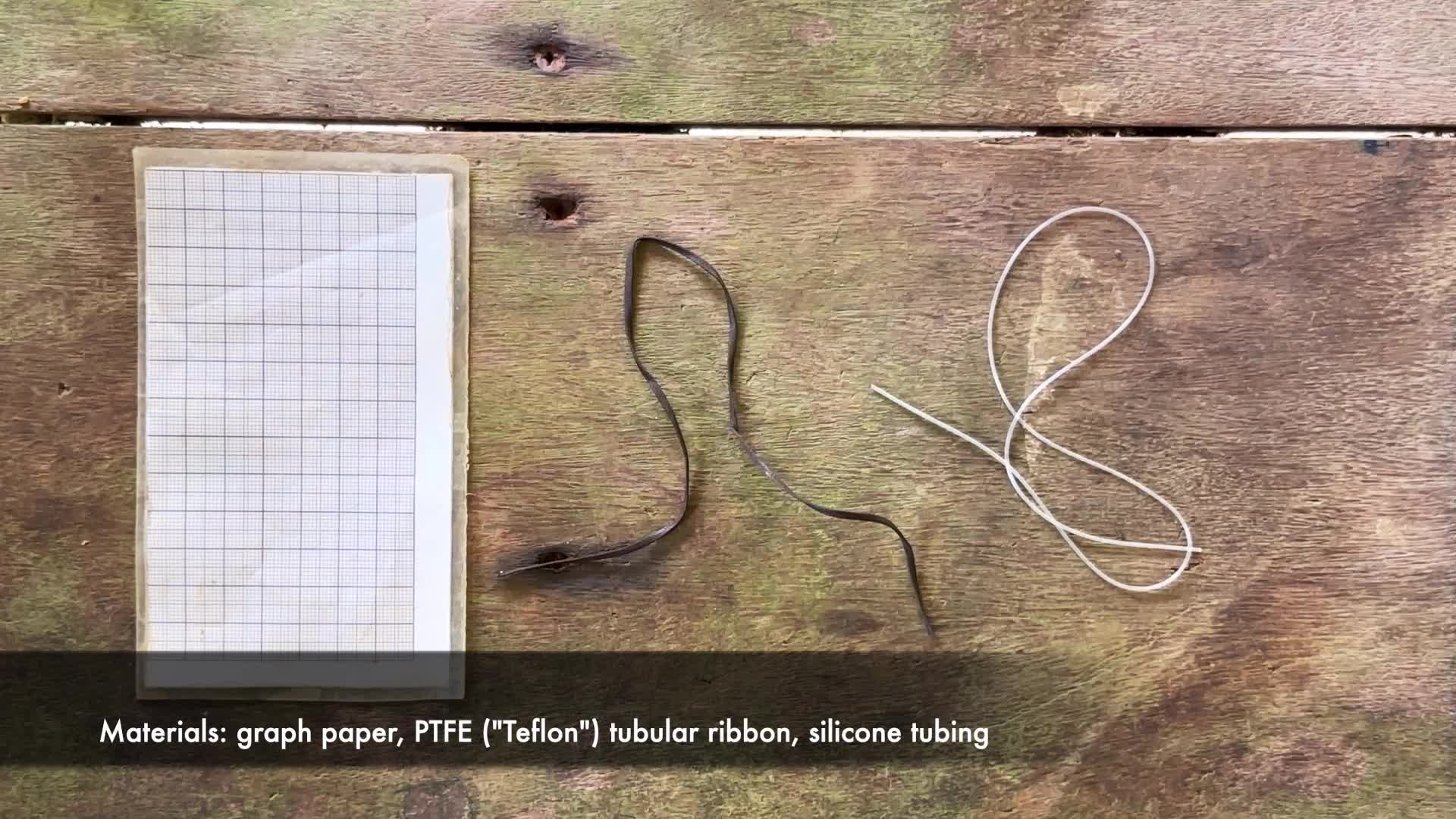
We also tested an alternative attachment approach by inserting the silicone tubing into a tubular polytetrafluoroethylene (PTFE; Teflon) ribbon sleeve. PFTE ribbons have a particularly low friction and are a standard attachment material in falconry and avian telemetry (Kenward, 2001). Based on recent experience, this approach reduces skin abrasion in the poison frog Dendrobates tinctorius. The PTFE ribbon can be sourced as 11 mm (0.44 inch) tubing tape designed for telemetry applications(e.g, Teflon tape, Ecotone Telemetry, Poland, https://en.ecotone.com.pl/produkty/tasma-teflonowa-do-telemetrii-11mm-044-cala--1metr.html).
Signal detection equipment
- HDF handheld transceiver (R9, Recco AB, Lindigö, Sweden; catalog number: D 99B)
- Radio receiver (e.g., Biotracker, Lotek Wireless, Newmarket, ON, Canada; catalog number: BIOTRACKER30 14)
- Three-element portable Yagi antenna (e.g., Lotek LITEFLEX 3-Element VHF Yagi Antenna)
Mapping the Study Area
- High precision compass with bearing measurement window (e.g., Suunto KB-20/360R G Yellow Compass. Vantaa, Finland. Link)
- Laser range finder (e.g., Bosch DLE 50 Professional Laser Rangefinder, Leinfelden-Echterdingen, Germany. Link)
- GNSS/GPS device (e.g., Garmin handheld or smartphone)
- Labeling tape or flagging tape
- Waterproof permanent marker
- Wooden, plastic, or metal stakes
- PVC tubes or tripod systems
- Measurement target constructed from PVC tubing and a centered plastic plate (recommended)
Troubleshooting
Problem
Weak or inconsistent HDF signal. Possible cause: Antenna length too short; poor diode connection; broken wire; incorrect diode polarity; frog hidden under logs, rocks, or water.
Solution
Verify electrical connections and diode polarity before deployment. Maintain total dipole length close to the recommended resonance length (~17 cm when possible). Inspect tags regularly for breakage and check under logs, rocks, or water bodies.
Problem
Frequent false HDF detections. Possible cause: Signal reflections from electronic devices, metallic structures, wet surfaces, or dense urban environments.
Solution
Avoid using HDF near electronic equipment when possible. Move nearby devices away from the detector (e.g., place your phone on your back while the detector is in front). Confirm detections from multiple directions before approaching the animal.
Problem
Difficulty localizing VHF-tagged frogs at close range. Possible cause: VHF signals become less directional at short distances.
Solution
Reduce receiver gain or attenuate the signal if possible. Approach slowly while frequently changing antenna orientation. If the signal remains difficult to localize, disconnect the antenna and scan the area using only the antenna cable. If further attenuation is required, disconnect the antenna cable as well and use the receiver alone to scan at close range.
Problem
Reduced VHF detection range. Possible cause: Antenna trimmed excessively short; depleted battery; water, rocks, walls, other solid structures, and hilly terrain can be a problem.
Solution
Test antenna length and detection range before deployment. Replace depleted transmitters and avoid excessive antenna shortening.
Problem
Harness slipping or rotating. Possible cause: Belt too loose; inappropriate harness design for the species' body shape.
Solution
Adjust the belt length to improve the fit around the waist. Consider using the double-strap design for species with a large waist-to-thigh circumference ratio.
Problem
Skin abrasion or irritation. Possible cause: Friction, exposed knots or rough edges, prolonged deployment.
Solution
Ensure all knots, adhesive residues, and sharp edges face away from the skin. Consider adding PTFE (Teflon) ribbon around the silicone tubing. Monitor frogs regularly and remove tags if irritation develops.
Problem
Frog entanglement with the antenna. Possible cause: Antenna positioned downward.
Solution
Orient antennas posteriorly along the dorsum and away from the body. Monitor tagged individuals regularly to ensure rapid release if entanglement occurs.
Problem
Tag loss. Possible cause: Belt fitted too loosely; cotton weak points breaking earlier.
Solution
Test harness fit before release and monitor tagged individuals regularly.
Problem
Abnormal frog behavior after tagging. Possible cause: Harness too tight; tag heavy; stress from handling
Solution
Minimize handling time and verify that frogs move normally before release. Remove or adjust improperly fitted tags.
Problem
Rapid battery depletion in VHF transmitters. Possible cause: High pulse rate; high TPO; continuous transmission cycle.
Solution
Lower pulse rate or TPO when long-term tracking is required. Consider programmed duty cycles to extend battery life.
Before start
Choose your best method
Table 1: Main differences between Harmonic Direction Finding (HDF) and Very High Frequency (VHF) telemetry techniques.
| A | B | C | |
| Harmonic Direction Finding (HDF) | Very High Frequency (VHF) | ||
| Tag type | Passive reflector (diode-based), also known as HDF transponder tag | Radio transmitter, also known as VHF transmitter | |
| Power source | No battery required | Small battery | |
| Signal emission | Reflects the signal from a handheld transceiver | Emits its own signal | |
| Signal rate and directionality | Continuous signal; strongly directional at close range | Pre-determined pulse rate, less directional, especially at close range | |
| Signal attenuation | Strongly attenuated and reflected by water and solid objects | Less attenuated and reflected by solid objects and water | |
| Signal range in the field (tropical forest) | Typically ~3–15 m (avg ~8 m), depending on the antenna length, material, orientation, and animal microhabitat. | Typically ~ 50 – 120 m (avg ~80 m, max ~ 200 m), depending on antenna length, transmitter power output (TPO), and animal microhabitat | |
| Individual identification | No unique signal; requires visual identification (e.g., color tags) | Unique frequency per tag | |
| Weight | Very light (<0.1 g) | Heavier (>0.3 g) | |
| Suitability | Smaller frogs (~1–3 g); short-range tracking | Larger frogs (>3 g); longer-range tracking | |
| Cost per tag | Lower (~5 - 20 USD) | Higher (~175 USD) | |
| Cost per signal detection kit | Higher (~3000 - 6000 USD for transceiver from RECCO AB) | Lower (~1000 - 3000 USD for receiver and antenna, depending on suppliers) | |
| Tag battery life | No battery required | Depends on tag size and pulse rate; ~10 - 20 days typical for the smallest tags | |
| Limitations | Short signal range, no unique tag signals, false signals from all electronics, and a more expensive receiver | Heavier tags, more difficult localization at close range, limited battery life, and higher tag cost |
Important note: Tag weight, size, and antenna length should be minimized as much as possible. Select tags based on the frog’s weight, size, ecology, locomotion, microhabitat, and available funds. No universally accepted transmitter-to-body-mass threshold exists for amphibians. A review of amphibian biotelemetry studies reported transmitter weight ranging from 0.8–18.4% of body mass, with most studies remaining below 10%, although this threshold lacks strong empirical justification (see Altobelli et al., 2022). In frogs, both tag weight and antenna length should be carefully considered, as they may influence movement and behavior. As a general guideline, tagging very small individuals (e.g., <1.5 g) is not recommended unless necessary, as tag burden and antenna size may disproportionately affect locomotion and behavior. Always test tags under field conditions before deployment and assess, document, and report their effects on animal movement and behavior before scaling up the study. Using HDF in urban environments is not recommended because high levels of signal interference from electronic devices can result in frequent false detections.
HDF transponder tag assembly
Step 1: Prepare the wires (Figure 2; see note on antenna length)
Cut two pieces of wire:
- One 3 cm length (short antenna).
- One 14 cm length (long antenna)
Figure 2. Wire pieces
Note on antenna length and configuration
For RECCO receivers tuned at ~9 MHz and HDF transponder tags constructed with D-1 Schottky diodes, the optimal total dipole length (combined antenna length) is ~17 cm, which maximizes resonance frequency and signal strength. A symmetrical configuration (~8.5 cm + 8.5 cm) provides ideal signal balance; however, many field applications require an asymmetric design with one short and one long antenna. In practice, this total length can be distributed asymmetrically between the two antenna segments. Based on our experience, effective configurations include ~14 cm (long antenna) and ~3 cm (short antenna). The short antenna can be further reduced (e.g., ~2 cm) to accommodate smaller individuals, with the excess length incorporated into the waistband/belt. The long antenna may also be reduced (e.g., ~12 cm), resulting in a total dipole length of ~14 cm with acceptable performance. However, shorter lengths may result in a rapid decline in signal strength due to reduced resonance with the 9 MHz transceiver.
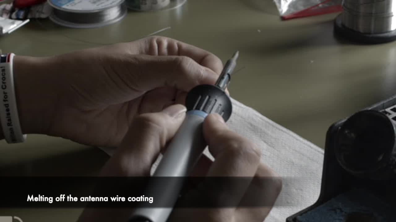
Step 2: Strip the pieces of wire (Figure 3)
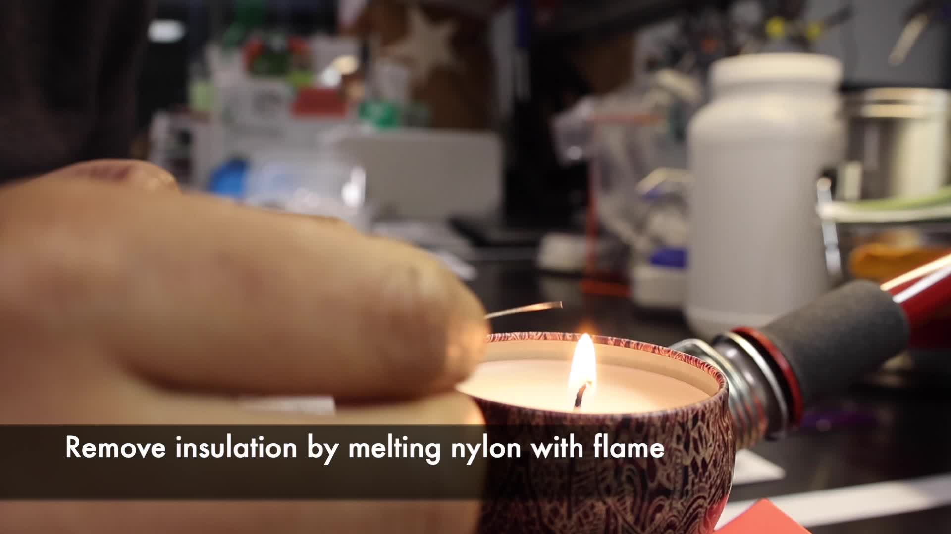
Because the wire is nylon-coated, remove the insulation by melting the nylon with heat or a flame in the areas that will contact the diode (taking care not to expose more wire than necessary).
- Strip a few millimeters from the middle of the short wire.
- Strip a few millimeters from one end of the long wire.
Figure 3. Wire stripped at one end and in the middle. The blue arrow indicates the wire before stripping, and the purple arrow indicates the wire after stripping.
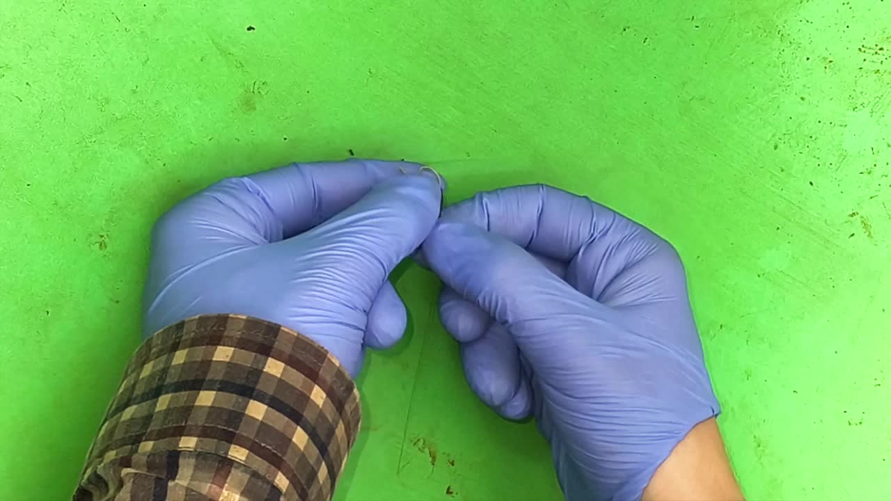
Step 3: Hold materials in place
Use a small piece of double-sided tape to help fix the diode and the wires in place. This helps keep everything steady while applying the silver conductive epoxy adhesive (Figure 4a). For hot soldering, use a small self-closing pair of forceps. The diode has an anode (+) and a cathode (–) pole, and its orientation can influence signal performance. In most diodes, the cathode is indicated by a colored or metallic band; in RECCO D-1 diodes, it is marked with a gold band. Based on our testing, signal strength was higher when the long antenna was connected to the cathode and the short antenna to the anode. Diode polarity can also be verified using a multimeter before assembly (Figure 4b–c).
Figure 4. Assembly process of the diode and antenna. (a) Temporary fixation of the diode and wires using double-sided tape. (b) Verification of diode polarity using a multimeter prior to assembly. (c) Final antenna configuration showing the long antenna connected to the cathode and the short antenna connected to the anode to maximize signal strength.
Step 4. Bond the diode to the antenna wire
The diode can be attached to the antenna wire using one of two methods: (A) conductive silver epoxy or (B) hot soldering. Select the method most appropriate for your materials and expertise.
Sub-step A: Contact bonding with conductive silver epoxy (Figure 5)
The 8331D Silver Conductive Epoxy is a 2-part adhesive, consisting of Part A (Epoxy Resin) and Part B (Hardener), both filled with silver powder to provide high electrical conductivity. To prepare the epoxy, dispense equal parts (1:1 ratio; Part A and Part B) onto a flat surface and mix thoroughly until a uniform silver-gray paste is obtained (Figure 5a). Use the mixture within 10 minutes.
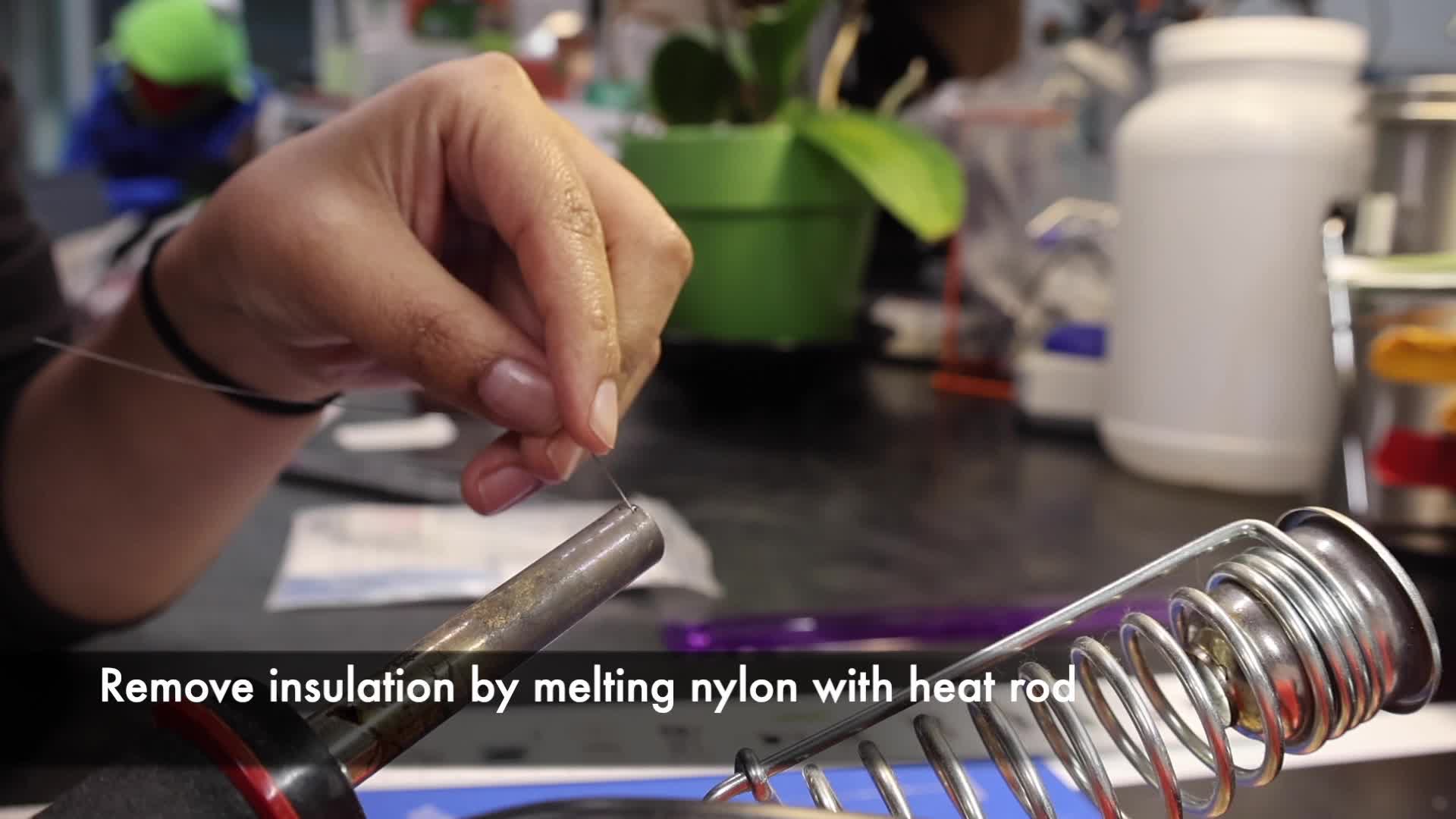
Using a small toothpick, syringe, or pipette tip, apply the paste to the contact points between the diode and the wires. Important: Ensure that the short and long wires remain electrically isolated except through the diode (Figure 5c). Direct contact between the wires will short the circuit and lower the tag resonance.
Figure 5. Close-up view of conductive epoxy application during assembly of the HDF transponder tag. (a) Uniform conductive paste after mixing. (b) Diode and antenna in place. (c) Epoxy is applied to connect each wire to the diode. The wires must remain electrically isolated from each other except through the diode (region inside the pink rectangle).
Sub-step A: Cure and allow bonding (Figure 6)
Curing is the chemical hardening process that transforms the epoxy paste into a solid bond. To cure the assembly, leave the tag undisturbed to dry overnight. After curing, carefully remove it from the double-sided tape and use a blade to trim any excess material around the tag to make it smaller and more comfortable for the frog, keeping only the portions necessary to maintain a stable electrical connection between the diode and the wires.
Figure 6. HDF tag prepared with conductive silver epoxy after curing. (a) Hardened conductive epoxy overnight. (b) Tag after trimming excess material to reduce size and improve comfort, while preserving the electrical connection between the diode and the wires.
Sub-step B: Contact bonding with hot soldering
Apply flux paste to the stripped section of the antenna wire (aggressive acid-based flux provides stronger bonding for stainless steel compared to standard rosin flux). Pre-tin the contact points of the antenna and diode by briefly melting a small amount of solder onto each contact using the soldering iron. Join the antenna and diode at the contact point by applying the soldering iron just long enough to reflow the solder and create the connection. Keep heating time very short (~1–3 s) to avoid overheating the diode. When using aggressive acid-based flux, it is recommended to clean the contacts with distilled water and isopropyl alcohol after soldering to prevent corrosion.
Step 5: Add silicone protection and color coding
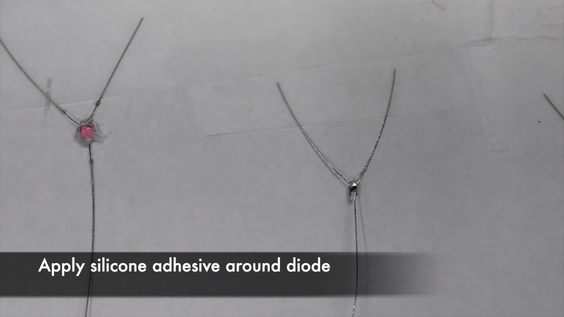
Once the tag has been trimmed and all components are in place, apply a thin layer of fast-curing silicone adhesive (we recommend SIL-PoxyTM, Smooth-On, Inc.) around the diode. This layer protects the assembled tag and the contacts from breaking and environmental elements.
Before the silicone fully dries, place a small piece of colored marker (paper or plastic) on the top to give each tag a unique color identifier (Figure 7). You could use a single color or a combination of two colors to create additional unique tags.
Allow to dry completely.
Figure 7. Protection and color coding of the HDF transponder tag. Silicone adhesive is applied around the diode to protect the assembly and a piece of color for unique identification.
VHF Transmitter Preparation
Step 1: Obtain transmitters
VHF transmitter tags can be purchased directly from multiple companies, including Lotek Wireless (https://www.lotek.com/), Holohil (https://www.holohil.com/), and Plecotus Solutions GmbH (https://plecotus-solutions.de/en/transmitters/). For illustration, we used freshwater Nanotags from Lotek Wireless Inc and custom-ordered tags from Plecotus Solutions.
Step 2: Customize tags
Manufacturers can provide specific modifications upon request.
- Tag weight: Tag weight depends on the battery size. Choose the lightest tags possible with sufficient battery life for your study.
- Pulse rate/burst interval: Pulse rate determines how many times the signal is emitted per second (bps) or minute (bpm). A higher pulse rate is easier to localize, but it reduces battery life.
- Transmitter power output (TPO): Some suppliers allow you to customize the TPO. Higher TPO increases detection range but reduces battery life.
- Battery life: Battery life depends on the pulse rate and the TPO.
- Programming: Some suppliers offer programmed tags to a specific duty cycle (e.g., 12 h ON / 12 h OFF) to extend battery life.
- Attachment hole: Request a small tube in the tag to allow insertion of silicone tubing or a thread for attachment.
- Antenna material: Some suppliers offer different antenna materials. For small frogs, select the most flexible material over the thinnest one.
- Antenna trimming: The antenna wire is typically 16 cm when shipped. Trim it as short as possible while testing that the detection range is sufficient for your study and species. The antenna length between 8 and 12 cm is typically sufficient.
Tag attachment design
Several methods can be used for attaching tags to frogs, and the most appropriate design should be selected based on the species’ anatomy and behavior. In poison frogs, cephalic amplexus and dorsal tadpole transport make waist-mounted harnesses particularly suitable because they minimize interference with natural behaviors.
Sub-step A: Design 1 - Belt with a single strap harness (single-strap harness; steps 1–3)
The single-strap harness consists of a circular silicone belt positioned around the waist, with an additional strip of tubing running between the thighs to stabilize the tag on the back and prevent rotation. During tag assembly, a cotton thread is used to create weak points, ensuring eventual release of the tag if it is not recovered (Figure 8–9).
Step 1: Prepare the waist belt
Cut a piece of silicone tubing to form the circular belt around the frog’s waist (Figure 8a).
Belt length should be adjusted according to species size. For example, we used:
- 18–20 mm for Ameerega shihuemoy (snout vent length SVL: 20.4–25.2 mm; mass: 0.8–1.4 g)
- 22–25 mm for Allobates femoralis (SVL: 20.0–29.1 mm; mass: 1.0–2.3 g)
- 22–24 mm for Oophaga sylvatica (SVL: 20.7–29.6 mm; mass: 1.8–2.8 g)
- 26–32 mm for Dendrobates tinctorius (SVL: 32.3–43.0 mm; mass: 2.9–6.2 g)
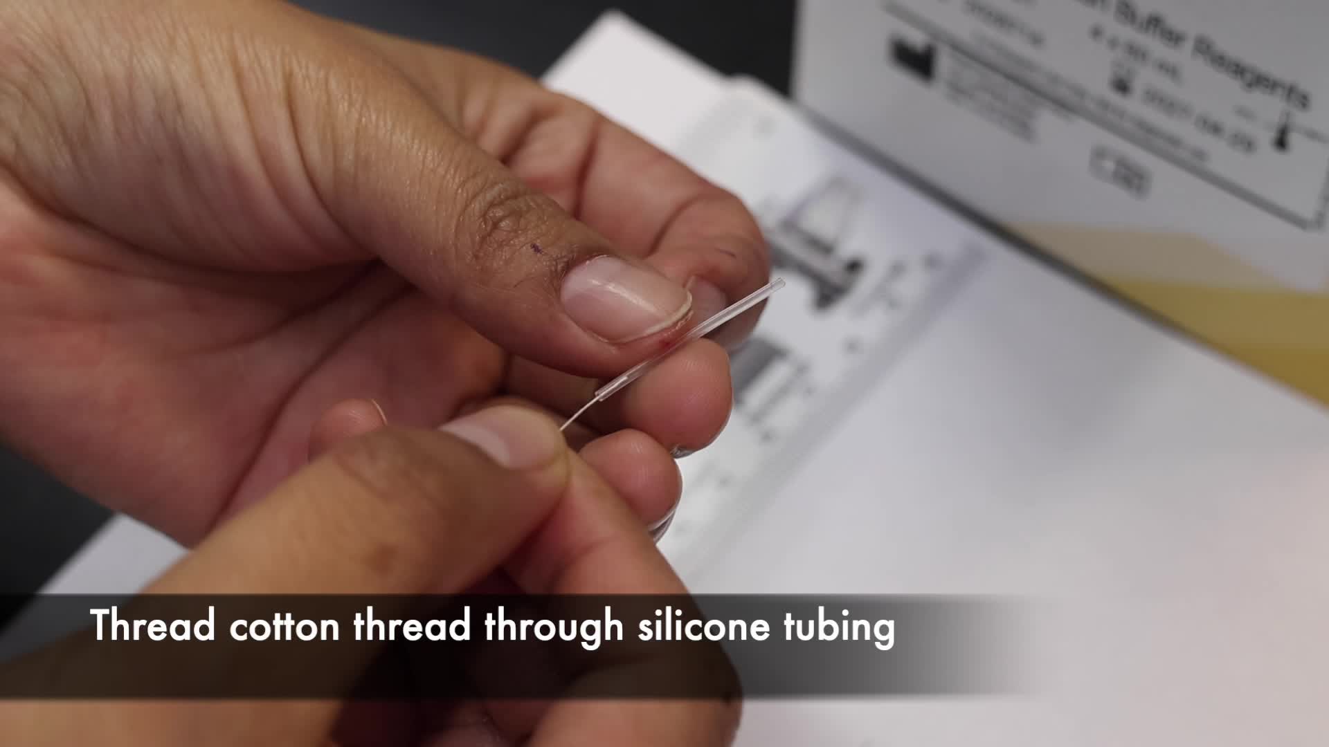
Thread a piece of cotton thread through the tubing (Figure 8b).
Step 2: Attach the HDF transponder tag to the belt
At the midpoint of the tubing, create a small opening with a scalpel or a razor blade (Figure 8c). Insert the short transponder wire through the opening so that it passes inside the tubing and exits near both ends (Figure 8d–f).
If needed, trim excess antenna wire using a wire-cutter.
Use the exposed wire ends together with the cotton thread to secure and close the tubing into a circular loop, forming the waist belt (Figure 8g–h).
Step 3: Add the stabilizing strap
Cut a shorter piece of tubing (~15 mm).
Using a needle, pass a piece of cotton thread (tied with three knots at one end) through the tubing from the back of the belt, near the diode (Figure 8i–j), then thread it through the shorter tubing segment (Figure 8k).
Tie the stabilizing strap to the belt thread to create the single-strap (“panty-style”) harness. (Figure 8l).
Figure 8. Belt with a single strap harness tag attachment design. Photographs showing: (a) components of the attachment design (including silicone tubing and the assembled HDF transponder tag); (b) threading a piece of cotton thread through the tubing; (c) creating a small opening at the midpoint of the tubing using a scalpel blade; (d) inserting the transponder wire through the opening in the tubing; (e–f) routing the wire through the belt so that it exits near both ends; (g–h) securing and closing the tubing into a loop using the exposed wire end and cotton thread to form the belt; (i) passing thread through the tubing from the back of the belt near the diode; (j) showing the three thread segments: two emerging from the belt and one for the stabilizing strap; (k) threading the shorter piece of tubing used as the stabilizing strap; and (l) tying the stabilizing strap to the belt to create the single-strap harness.
Figure 9. Finalized HDF transponder tag with a single-strap design, showing dorsal, (a) lateral (b), and ventral (c) views of the completed tag.
Final orientation and safety considerations
The orientation of the antenna can influence both signal performance and animal safety. The long antenna should not extend straight downward, as this may increase the risk of hind-limb entanglement during movement. Whenever possible, position the antenna along the body axis (e.g., posteriorly along the dorsum) and minimize protruding wire segments. Although the single-strap design lies close to the cloacal region, successful egg laying and fertilization have been observed in tagged frogs (Fischer et al., 2020; Pašukonis et al., 2022; Serrano-Rojas et al., 2026). This design has been successfully used in several poison frogs, including Allobates femoralis (Beck et al., 2017; Fischer et al., 2020; Pašukonis et al., 2014, 2022), Ameerega macero (Serrano-Rojas et al., 2026), Ameerega trivittata (Pašukonis et al., 2018, 2019), Ameerega shihuemoy (Serrano-Rojas et al., 2026), Dendrobates tinctorius (Pašukonis et al., 2019, 2022), and Oophaga sylvatica (Pašukonis et al., 2022).
Use with VHF transmitters
The single-strap harness can also be adapted for VHF transmitters. In this configuration, the cotton thread is passed through the custom-made hole in the transmitter and then threaded through the center of the silicone tubing. The thread is pulled from both ends and tied to form a circular belt or waistband. A second strip of silicone tubing is then attached at the center to complete the single-strap harness design.
PTFE (Teflon) ribbon modification
A tubular PTFE (Teflon) ribbon can be added around the silicone tubing to reduce skin friction and related injuries; however, this modification may be too bulky for the smallest species. To construct this version, insert the silicone tubing into the PTFE ribbon using a needle, then pass the cotton thread through the tubing and through the transmitter attachment hole. Tie the thread ends to form the waist belt. A second piece of silicone tubing is then attached as the stabilizing strap and secured with knots reinforced using small amounts of silicone adhesive.

Sub-step B: Design 2 - Belt with leg straps (double-strap harness; steps 1–3)
The double-strap harness consists of a circular silicone belt with two attached silicone leg loops. The loops can be secured using silicone adhesive or cotton thread. This design is particularly useful for species in which the waist-to-thigh circumference ratio is large, making a waist-only belt more likely to slip or cause discomfort. Compared with the single-strap design, the double-strap harness also reduces contact with the cloacal region (Figure 10–11).
Step 1: Prepare the waist belt
Cut a piece of silicone tubing to form the circular belt around the frog’s waist (Figure 10a).
Belt length should be adjusted according to species size. For example, we used:
- 24–28 mm for Ameerega trivittata (SVL: 34.5–45.8 mm; mass: 3.5–7.4 g)
- 26–32 mm for Dendrobates tinctorius (SVL: 32.3–43.0 mm; mass: 2.9–6.2 g)
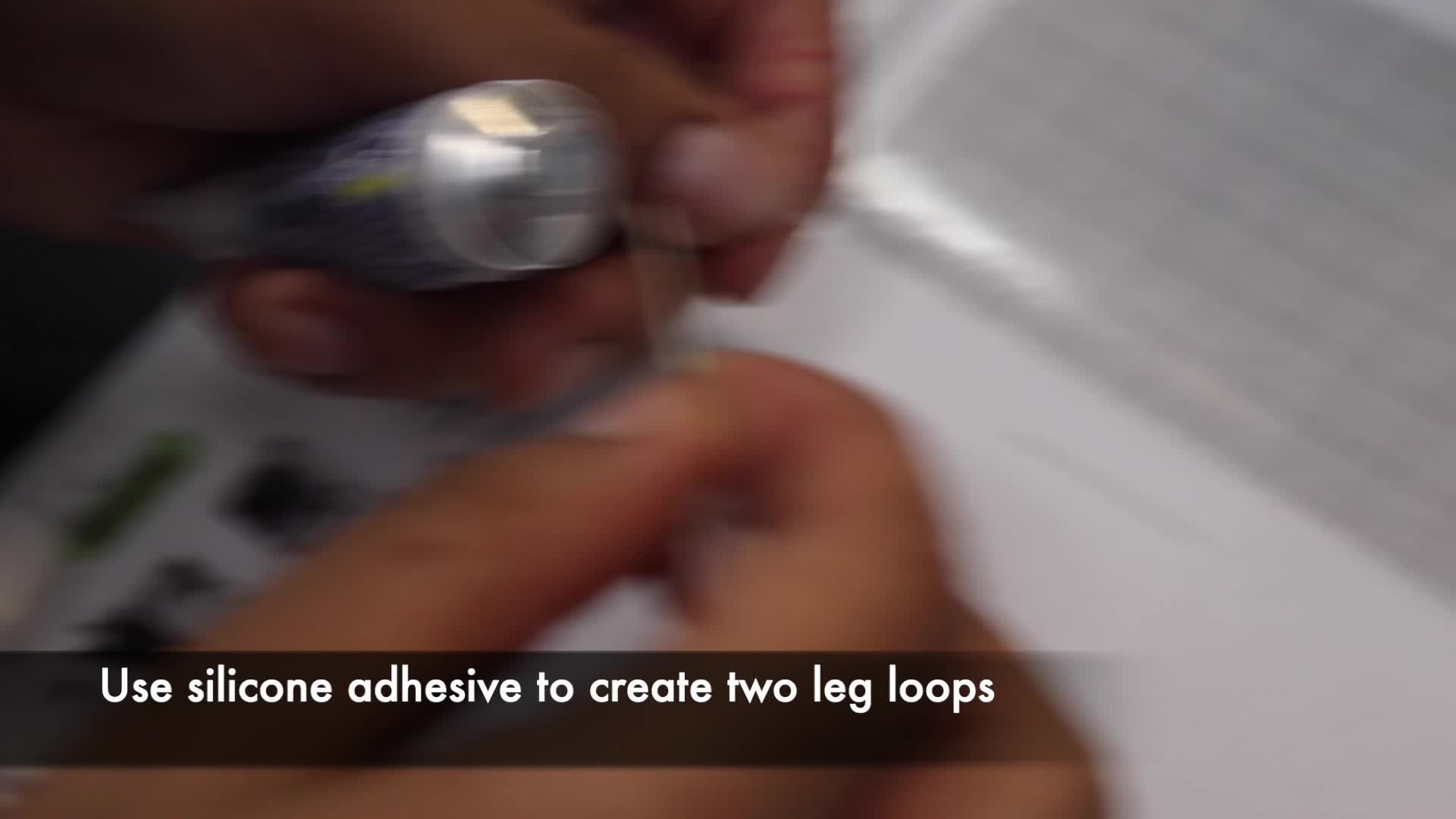
Step 2: Prepare the leg straps
Cut two pieces of silicone tubing (20–25 mm; Figure 10a), adjusting the length according to the species.
Shape each piece into a loop using a small amount of silicone adhesive (Figure 10b). Attach the leg loops to the belt using silicone adhesive, spacing them ~15 mm apart so they align with the frog’s hind legs (Figure 10c). Adjust spacing as needed based on the frog’s anatomy.
Alternatively, cotton thread can be used to form and attach the leg loops to the belt.
Step 3: Attach the VHF transmitter
Thread a piece of cotton string through the belt tubing (Figure 10d) and then through the custom hole in the VHF transmitter tag (Figure 10e).
Pull both ends of the thread and tie them to close the belt into a circular loop (Figure 10f).
Figure 10. Belt with leg straps (double-strap harness) attachment design. Photographs showing: (a) silicone tubing pieces for the belt and leg loops; (b) forming leg loops by joining the ends with silicone adhesive; (c) waist belt strap with attached leg loops; (d) threading cotton thread through the belt tubing; (e) passing the thread through the custom attachment hole in the VHF transmitter tag; (f) pulling and tying the thread to close the belt; (g) completed tag showing the frequency label and leg loop attachment points; and (h) the opposite side of the tag, showing the smooth surface intended to face the frog’s skin.
Figure 11. Finalized VHF transmitter with double-strap harness design showing dorsal (a), lateral (b), and ventral (c) views of the completed VHF transmitter tag.
Optional modification: PTFE (Teflon) ribbon
A tubular PTFE (Teflon) ribbon can also be incorporated to reduce skin friction and associated injuries. In this modification, silicone tubing is inserted into the PTFE ribbon before assembly. The belt portion is prepared following the same procedure described above. After threading cotton through the silicone tubing within the PTFE ribbon, two additional tubing pieces are prepared as leg straps. Using a needle and cotton thread, each strap is attached to the belt to form leg loops, and the knots are reinforced with silicone adhesive. Finally, the cotton thread ends are passed through the transmitter attachment hole and tied to close the belt, completing the double-strap harness.
Tag fitting on frogs
Guidelines
- Fit the harness using your chosen design
- Use powder-free nitrile gloves
- Minimize handling time (<10 min recommended)
- Place frogs in a net cage between handling steps whenever possible
- Always keep frog skin moist and protected throughout handling
- Avoid direct contact with dry or warm hands
Sub-step A: Single-strap fitting (steps 1–3)
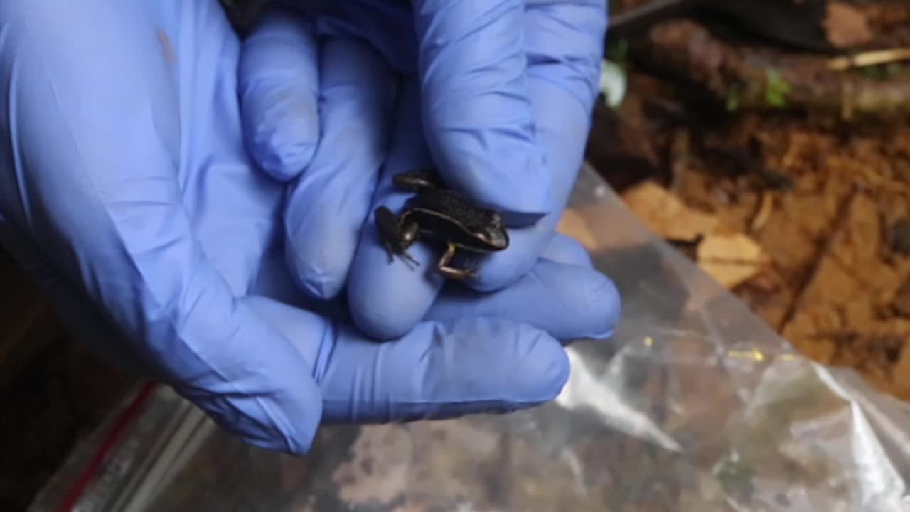
Step 1: Handle the frog safely (Figure 12)
- Gently grab the frog by holding the hind legs.
- Place a moist leaf or barrier between the handler’s hand and the frog to minimize heat transfer and stress.
Figure 12. Safe handling of frogs during HDF transponder tag attachment. The frog is gently held by the hind legs while a leaf or moist barrier is placed between the handler’s hand and the frog to minimize heat transfer and reduce stress.
Step 2: Insert the legs (Figure 13)
- Using your free hand, gently guide one foot through one opening of the harness until the loop rests around the lower leg (between the foot and the knee), without pulling it up to the thigh.
- Carefully repeat the procedure with the second foot.
Note: Frog legs are delicate but flexible; do not force the legs through the harness. Instead, gently guide each foot into the correct opening. Avoid handling frogs by the toes during fitting, as this may cause injury.
Figure 13. Step-by-step attachment of the HDF transponder tag using the single-strap harness design. (a) Tag held in one hand and the frog in the other. (b) Insert the first leg. (c) Position the loop around the lower leg between the foot and the knee. (d) Insert the second leg.
Step 3: Position the harness (Figure 14)
Once both feet are through the opening of the harness, gently pull the legs forward so the belt slides into position around the waist.
Critical note: The belt should fit snugly as it passes over the thighs to reduce the risk of tag loss. However, it should remain loose enough to slide over the thighs without causing injury or distress.
Figure 14. Frog fitted with the single-strap harness design. (a) Sliding the harness into position around the waist. (b) Lateral view. (c) Ventrolateral view. (d) Dorsal view.
Sub-step B: Double-strap fitting (steps 1–3)
Step 1: Handle the frog safely (Figure 15)
- Gently grab the frog by holding the hind legs.
- Place a moist leaf or barrier between the handler’s hand and the frog to minimize heat transfer and stress.
Figure 15. Safe handling of frogs during VHF transmitter tag attachment. The frog is gently held by the hind legs while a leaf or moist barrier is placed between the handler’s hand and the frog to minimize heat transfer and reduce stress.
Step 2: Insert legs into the harness loops (Figure 16)
- Using your free hand, gently guide both feet through one opening of the waist belt.
- Then, carefully guide each foot through its corresponding leg loop until the loop passes over the foot. Carefully repeat the procedure for the second leg.
Figure 16. Step-by-step attachment of the VHF transmitter tag using the double-strap harness design. (a) Transmitter held in one hand and the frog in the other; (b) inserting both feet through the waist belt opening; (c) guiding the feet through the corresponding leg loops while moving the belt upward along the legs; (d) sliding the waist belt and leg loops into their final position around the waist and thighs. Photographs show a captive individual of Dendrobates tinctorius (azureus morph) used for demonstration purposes only and not included in the telemetry study.
Step 3: Position the harness (Figure 17)
Once both feet are through the leg loops, gently slide the waist belt and leg loops upward until the belt reaches its position around the waist and the leg loops settle around the thighs.
Critical note: The waist belt should fit securely without being overly tight. The leg loops should fit loosely around the thighs but should not extend far enough to approach the knees. Proper fit allows free leg movement while helping maintain tag stability.
Figure 17. Frog fitted with the double-strap harness design. (a) Harness positioned around the waist. (b) Dorsal view. (c) Lateral view. (d) Ventral view. (e) Smooth, flat surface of the tag that will be in contact with the frog's skin.
Post-fitting procedures and release
Step 1: Rehydrate the frog
Immediately after fitting the tag, apply a small amount of clean rainwater to the frog to restore moisture that may have been lost during handling.
Step 2: Check tag attachment
Confirm that:
- There is no visible constriction or sign of distress.
- There is no skin damage.
- No sharp edges or knots are in contact with the frog’s skin.
- The tag is positioned on the dorsal surface of the frog.
- The tag lies flat against the frog’s body, with the antenna pointing away from the hind legs rather than downward, to avoid interfering with movement.
Step 3: Frog release and monitoring
Release the frog at the exact point of capture (depending on the project’s goals and study design) and observe its behavior after release. During observation, confirm:
- Normal locomotion (e.g., walking and jumping without impairment).
- No abnormal posture or distress.
- Tags remain securely positioned.
Important: If abnormal behavior is observed, recapture the frog and adjust or remove the tag as necessary.
Repeat the focal observations regularly and record the behavior. Some behaviors, such as hiding or scratching, may occur immediately after tagging but should decrease as the frog habituates to the harness. If abnormal behaviors or excessive hiding persist, remove the tag and reevaluate the harness design and fit.
Relocating frogs and spatial data collection
Relocating tagged individuals and recording their positions requires a standardized workflow to ensure accurate spatial measurements.
The general workflow includes:
- Selecting the appropriate spatial data collection method based on the required accuracy.
- Establishing and mapping a grid of reference points within the study area, when high spatial accuracy is needed.
- Relocating tagged individuals using telemetry.
- Recording frog positions relative to reference points.
- Converting field measurements into projected spatial coordinates.
- Exporting the spatial data for analysis.
This workflow can be broadly applied to small vertebrates and is illustrated here using poison frogs as an example.
Choosing an appropriate spatial data collection method
Before beginning a telemetry study, determine the level of spatial accuracy required to address the study questions. Lower spatial accuracy is often sufficient for studies focused on large-scale movements or general habitat use. However, studies investigating fine-scale movement trajectories, territoriality, or microhabitat selection of small amphibians often require meter- or sub-meter-level spatial accuracy.
For some applications, the positional accuracy provided by Global Navigation Satellite Systems (GNSS), such as GPS or GLONASS, may be sufficient. In these cases, frog locations can be recorded directly using GNSS-enabled devices, including handheld GPS receivers and smartphones with field data collection apps. GNSS accuracy depends on multiple factors, including receiver quality, satellite coverage, canopy density, terrain, and atmospheric conditions (Bene & Tomaštík, 2026; Lee et al., 2023). Professional-grade receivers operating in open areas with strong satellite coverage may achieve sub-meter accuracy. However, these systems are often prohibitively expensive and may still experience positional errors of several meters under dense tropical forest canopy. Consumer-grade GNSS devices typically provide positional accuracy of approximately 5–15 m. Although averaging multiple GNSS measurements from the same location can improve accuracy slightly, this level of precision is often insufficient for capturing fine-scale movements of animals with spatially complex behaviours at relatively small scales.
When higher spatial accuracy is required, traditional survey methods based on distance and bearing measurements are recommended. These approaches are particularly useful for studying animals that move over relatively small spatial scales within structurally complex habitats. Traditional survey methods have broad applications in ecological research and range from simple systems using a compass, measuring tape, notebook, and pencil to more advanced workflows incorporating digital theodolites, laser range finders, Geographic Information Systems (GIS), and GNSS receivers (Kenward, 2001; White & Garrott, 2012).
Here, we describe one practical workflow that relies on establishing a study plot with a grid of reference points, which are subsequently used to measure frog locations. Similar approaches have been used in previous studies of poison frog movement ecology (see Beck et al., 2017; Fischer et al., 2020; Pašukonis et al., 2022), and the grid method has been described in detail by Ringler et al. (2016).
Step 1: Define the study boundaries
Delimit the study area according to:
- Expected movement distances of the focal species.
- Habitat features relevant to the study design.
- Logistical constraints associated with tracking and relocation frequency.
Reference point spacing should be adjusted according to habitat complexity and the expected scale of animal movement. In poison frog studies, spacing reference points approximately 5–15 m apart is often sufficient to maintain accurate relocation measurements while minimizing survey effort. In dense vegetation or steep terrain, shorter spacing between reference points may improve measurement precision and facilitate relocation.
Step 2: Record the starting GNSS point
Use a GNSS device to record the coordinates of a starting point located centrally within the study area whenever possible.
To improve accuracy:
- Collect multiple GNSS readings from the same location and average the recorded coordinates using the device’s averaging function.
- Choose a location with minimal canopy obstruction whenever feasible.
This starting point serves as the origin for all subsequent spatial calculations and reference point establishment. Mark the point in the field using a wooden, plastic, or metal stake and a unique label (Figure 18).
Note: A local coordinate system can also be established using an arbitrary origin point (e.g., 0,0). However, recording a GNSS position allows the local survey grid to be connected to geographic coordinate systems and other mapped datasets.
Figure 18. Establishment of reference points. (a) Zoomed-in view of a grid of reference points showing the initial GNSS point marked with a red sun cross and all other reference points marked with black sun crosses. Reference points are spaced 5–15 m apart. (b) Example of a reference point in the field marked with a PVC tube. The white arrow indicates the label of the reference point.
Step 3: Establish reference points
Establish the first set of reference points relative to the starting point using:
- Distance measurement (m)
- Compass bearings (degrees)
- Slope inclination measurement when the terrain is steep.
Subsequent reference points are then established progressively from previously marked reference points. In practise, each newly established point becomes the origin for additional measurements and points, allowing the reference grid to expand across the study area (Figure 18b).
For each newly established reference point, record:
- The reference point ID from which the measurement was taken
- The measured distance
- The bearing
- The inclination angle when applicable.
Mark each reference point in the field using:
- Flagging tape
- Unique ID labels
- Wooden, plastic, or metal stakes when appropriate
Reference point establishment is typically most efficient with a minimum of two observers: one operating the compass and range finder from the known reference point, and the second positioning the target marker at the location of the new point.
Important note: Measurement accuracy can be substantially improved by standardizing instrument position and target height during surveying (Figure 19). While taking measurements:
Stand directly above the reference point
Position the compass and range finder at a consistent height using a tripod or PVC tube
Place the target marker at approximately the same height as the measuring instruments
This setup improves both bearing and distance accuracy and reduces variation caused by observer positioning. Targets can be constructed using simple field materials such as PVC tubes and plastic plates.
Whenever possible, periodically verify the accuracy of the reference grid by remeasuring distances and bearings between selected reference points. This helps identify cumulative measurement errors before they propagate throughout the study area.
Figure 19. Diagram of a setup used to improve the precision of distance and bearing measurements between reference points. A PVC tube positioned above the reference point supports the compass and laser range finder, while a second PVC tube with a centered target plate, used as the measurement target position, marks the location of the new reference point being established. Both structures are positioned at the same height to improve measurement consistency and accuracy.
Choose your telemetry method
Sub-step A: Relocating frogs using HDF telemetry (Steps 1–3)
Step 1: Begin search
Begin the search near the frog’s last known location.
Move slowly and carefully through the habitat to avoid disturbing the frog or damaging the surrounding vegetation and microhabitat.
HDF detection range depends strongly on antenna orientation, vegetation density, terrain structure, humidity, and the frog’s microhabitat. Frogs hidden beneath logs, rocks, dense roots, or water may produce weak or intermittent signals.
Step 2: Sweep the transceiver and detect the signal
Hold the transceiver steady and slowly sweep it in a smooth figure-eight pattern while moving through the search area, following the recommendations provided in the RECCO instruction manual (RECCO AB, Lindigö, Sweden). This movement improves signal detection and directional interpretation (Figure 20).
As signals are detected:
- Pause briefly
- Rotate the transceiver slowly
- Identify the direction of the strongest signal intensity
- Move gradually toward the estimated location.
Approaching the signal from multiple directions helps distinguish true detections from reflected or false signals. As the estimated location is approached, move laterally and in small circular paths around the signal source to refine the frog’s position while reducing the risk of stepping directly on the animal.
Step 3: Visually confirm the frog location
When possible, locate the frog visually and confirm the identity of the individual using the color-coded tag.
Note: Precise visual confirmation may not always be possible or necessary. In some applications, narrowing the signal source to a sufficiently small area may provide adequate spatial resolution for the study objectives.
Figure 20. HDF telemetry tracking technique in dense habitats. The researcher sweeps the transceiver in a figure-eight pattern to detect reflected signals from passive tags.
Sub-step B: Relocating frogs using VHF telemetry (Steps 1–4)
Step 1: Detect the signal
Begin the search near the frog’s last known location.
Turn on the receiver and tune it to the transmitter frequency assigned to the individual frog. Move carefully through the habitat while periodically scanning for signal detection.
Step 2: Determine signal direction
Rotate the directional antenna slowly through 360° and identify the direction of the strongest signal intensity.
VHF signals may fluctuate because of terrain structure, vegetation density, water, or signal reflection. When the signal direction is unclear, moving laterally or in parallel to the signal often helps clarify the direction of the transmitter.
Step 3: Move toward the signal
Walk gradually toward the strongest signal while frequently recalibrating the antenna direction (Figure 21).
As the receiver approaches the transmitter, progressively reduce the receiver gain if possible. At close range, VHF signals may become oversaturated and difficult to localize accurately.
Step 4: Locate the frog
Adjust the receiver gain as the signal strengthens, and locate the frog visually when possible.
Note: At close range, precise localization with VHF can be difficult, and visual confirmation may not always be possible or necessary. In these cases, move slowly in small circles around the estimated location to refine the signal. Using only the antenna cable (without the antenna attached) or the receiver alone can also help improve fine-scale localization.
Figure 21. VHF telemetry tracking using a directional antenna. Researcher rotating the antenna to determine the signal direction and locate the tagged frog.
Recording the data
Step 1: Identify the nearest reference point
Identify the closest reference point from which the frog's position can be accurately measured.
Step 2: Measure frog position
Record:
- The reference point ID
- The distance (m) from the reference point to the frog
- The bearing (degrees)
- Slope inclination when applicable.
Measurements should be recorded immediately after relocation to minimize transcription errors.
Step 3: Record frog metadata
Record additional information relevant to the study objectives, including:
- Frog ID
- Date
- Time
- Observer
- Behavior
- Perch height
- Microhabitat categories
- Weather conditions when relevant
Step 4: Data entry
Option 1: Paper datasheets
Record all measurements in waterproof field notebooks or printed waterproof datasheets.
Option 2: Digital data collection
Record measurements directly into a handheld digital device using a field data collection application (e.g., Epicollect5). Digital recording is recommended because telemetry studies typically generate large numbers of repeated relocation records per individual.
Whenever possible, verify all entries immediately after recording to minimize data entry errors and ensure measurements are associated with the correct individual and reference point.
Convert bearing and angle measurements into spatial coordinates
Reference points and frog locations are initially recorded as distances (in meters) and bearings (in degrees) relative to previously established reference points. To perform spatial analysis, these measurements must be converted from polar coordinates (distance and angle) into Cartesian coordinates (x, y).
Step 1: Establish the coordinate origin
Begin with either:
- The projected coordinates of the starting GNSS point, or
- An arbitrary local coordinate origin (0,0).
Projected coordinates are typically expressed as:
- Easting (E₀), i.e., x-coordinate
- Northing (N₀), i.e., y-coordinate
These coordinates serve as the anchor for calculating all subsequent locations.
Step 2: Convert distance and bearing measurements into Cartesian X and Y offsets.
For each reference point and frog relocation, calculate:
X=d * sin(θ), Y=d * cos(θ)
Where:
- d = distance (m)
- θ = bearing (degrees clockwise from north)
- X = easting offset
- Y = northing offset
Important: Compass bearings should be corrected for magnetic declination, either during field measurements or during post-processing, to account for the difference between Magnetic North and True North. Declination values for a specific locality can be obtained using the NOAA Magnetic Field Calculator.
If the study area contains steep terrain, slope inclination can also be incorporated into the calculations to improve coordinate accuracy.
Step 3: Calculate the coordinates for reference points
For points measured directly from the origin:
- Easting = E0 + X
- Northing = N0 + Y
For points measured relative to previously established reference points, use the already calculated coordinates of the known reference point, and add the corresponding X and Y offsets.
Repeat this process iteratively until all coordinates have been calculated for all reference points.
Step 4: Calculate coordinates for frog locations
For each frog relocation:
- Identify the corresponding reference point
- Calculate the X and Y offsets from the measured distance and bearing
- Add the offsets to the coordinates of the selected reference point.
The resulting Easting and Northing coordinates can then be exported for spatial analyses and mapping (Table 2), including visualization of movement paths and estimation of home ranges (Figure 23).
Worked example
A frog located 5 m from reference point A12 at a bearing of 90° would produce the following offsets:
- X = 5 * sin(90°) = 5,
- Y = 5 * cos(90°) = 0
If A12 has coordinates:
- Easting = 238974.55
- Northing = 8583533.05
Then the frog coordinates become:
- Easting = 238979.55
- Northing = 8583533.05
Final verification:
Plot all reference points and frog locations to verify that locations are spatially consistent and fall within the expected study area (Figure 22). Check the dataset point by point to identify outliers and potential measurement or recording errors.
Note: Unlike GNSS-based relocation methods, this approach is sensitive to human measurement and data entry errors. Errors introduced while establishing reference points are particularly important because all subsequent frog and reference locations depend on them. Careful verification at each step is therefore essential. However, this method avoids cumulative GNSS positioning error and can provide centimeter- to meter-scale spatial resolution, depending on measurement precision.
Coordinate systems and projection
GNSS devices typically record locations in geographic coordinates (latitude and longitude). For accurate distance calculations and spatial analyses, these coordinates should first be converted into a projected coordinate system expressed in meters, such as Universal Transverse Mercator (UTM).
In this protocol, geographic coordinates were converted into UTM coordinates prior to analysis to obtain:
- Easting coordinates (m)
- Northing coordinates (m).
This conversion can be performed:
- In GIS software (e.g., QGIS)
- Directly in R
- Using online coordinate conversion tools.
Alternatively, if absolute geographic positioning is unnecessary, a local coordinate system can be established by defining the starting point as:
- E₀ = 0
- N₀ = 0
All subsequent positions are then calculated relative to this local origin.
Example R code for coordinate calculation
# Example data (replace with your own)
data <- data.frame(
distance = c(10, 20, 15),
angle = c(30, 120, 270), # degrees clockwise from north
E0 = 238974.55, # starting easting
N0 = 8583533.05 # starting northing
)
# Convert angles to radians and calculate Cartesian offsets
data <- data %>%
mutate(
angle_rad = angle * pi / 180,
X = distance * sin(angle_rad),
Y = distance * cos(angle_rad),
Easting = E0 + X,
Northing = N0 + Y
)
Example: Poison frog telemetry project
The following examples illustrate how converted recolations can be visualized and used for movement analyses in a poison frog telemetry study.
Figure 22. Zoomed-in view of a grid of reference points showing frog locations as colored points, with a different color representing each frog. The figure shows tracking data collected over ten days for three poison frogs in the Amazon.
Table 02 – Conversion of frog relocation measurements into projected spatial coordinates. Reference points are first assigned UTM coordinates, either directly from the origin or iteratively from previously established reference points using calculated X and Y offsets. Distance and bearing measurements from these reference points are then converted into easting (X) and northing (Y) offsets for each frog relocation. These offsets are added to the corresponding reference point coordinates to obtain the final projected spatial coordinates for each frog location.
Figure 23. Example movement path and home range of a tagged frog. The map shows frog relocations (pink circles), reference points (sun crosses), and the estimated home range (dark polygon), illustrating fine-scale movement patterns collected over ten days of tracking.
Protocol references
Altobelli, J. T., Dickinson, K. J. M., Godfrey, S. S., & Bishop, P. J. (2022). Methods in amphibian biotelemetry: Two decades in review. Austral Ecology, 47(7), 1382–1395. https://doi.org/10.1111/aec.13227
Beck, K. B., Loretto, M.-C., Ringler, M., Hödl, W., & Pašukonis, A. (2017). Relying on known or exploring for new? Movement patterns and reproductive resource use in a tadpole-transporting frog. PeerJ, 5, e3745. https://doi.org/10.7717/peerj.3745
Bene, K., & Tomaštík, J. (2026). Evaluation of Accuracy and Usability of Low-Cost GNSS Receivers Under Tree Canopy: Impact of Vegetation and Seasonal Changes. Geomatics, 6(2), 34. https://doi.org/10.3390/geomatics6020034
Boyarski, V. L., Rodda, G. H., & Savidge, J. A. (2007). Evaluation of Harmonic Direction-Finding Systems for Detecting Locomotor Activity. The Journal of Wildlife Management, 71(5), 1704–1707.
Fischer, M.-T., Ringler, M., Ringler, E., & Pašukonis, A. (2020). Reproductive behavior drives female space use in a sedentary Neotropical frog. PeerJ, 8, e8920. https://doi.org/10.7717/peerj.8920
Groffen, J., Hoskin, C. J., Siderhurst, M. S., & Menz, M. H. M. (2025). Tracking movement, home range, and microhabitat use in a small terrestrial breeding frog using harmonic direction-finding technology. Wildlife Research, 52(7), WR24111. https://doi.org/10.1071/WR24111
Kenward, R. (2001). A manual for wildlife radio tagging. Radio tracking and animal populations. Animal Conservation Forum, 5(3), 259–260. https://doi.org/10.1017/S1367943002212317
Lee, T., Bettinger, P., Merry, K., & Cieszewski, C. (2023). The effects of nearby trees on the positional accuracy of GNSS receivers in a forest environment. PLOS ONE, 18(3), e0283090. https://doi.org/10.1371/journal.pone.0283090
Lovei, G. L., Stringer, I. A. N., Devine, C. D., & Cartellieri, M. (1997). Harmonic radar—A method using inexpensive tags to study invertebrate movement on land. New Zealand Journal of Ecology, 21, 187–193.
Pašukonis, A., Loretto, M.-C., & Hödl, W. (2018). Map-like navigation from distances exceeding routine movements in the three-striped poison frog (Ameerega trivittata). Journal of Experimental Biology, 221(2), jeb169714. https://doi.org/10.1242/jeb.169714
Pašukonis, A., Loretto, M.-C., & Rojas, B. (2019). How far do tadpoles travel in the rainforest? Parent-assisted dispersal in poison frogs. Evolutionary Ecology, 33(4), 613–623. https://doi.org/10.1007/s10682-019-09994-z
Pašukonis, A., Serrano-Rojas, S. J., Fischer, M.-T., Loretto, M.-C., Shaykevich, D. A., Rojas, B., Ringler, M., Roland, A. B., Marcillo-Lara, A., Ringler, E., Rodríguez, C., Coloma, L. A., & O’Connell, L. A. (2022). Contrasting parental roles shape sex differences in poison frog space use but not navigational performance. eLife, 11, e80483. https://doi.org/10.7554/eLife.80483
Pašukonis, A., Warrington, I., Ringler, M., & Hödl, W. (2014). Poison frogs rely on experience to find the way home in the rainforest. Biology Letters, 10(11), 20140642. https://doi.org/10.1098/rsbl.2014.0642
Ringler, M., Mangione, R., Pašukonis, A., Rainer, G., Gyimesi, K., Felling, J., Kronaus, H., Réjou-Méchain, M., Chave, J., Reiter, K., & Ringler, E. (2016). High-resolution forest mapping for behavioural studies in the Nature Reserve ‘Les Nouragues’, French Guiana. Journal of Maps, 12(1), 26–32. https://doi.org/10.1080/17445647.2014.972995
Rowley, J. J. L., & Alford, R. A. (2007). Techniques for tracking amphibians: The effects of tag attachment, and harmonic direction finding versus radio telemetry. https://doi.org/10.1163/156853807781374755
Serrano-Rojas, S. J., Pašukonis, A., Gonzalez, M., Rodriguez, C., Usto, R. F. C., Carazas, A., García, C. S., Zolorzano, J. P., Arcila-Pérez, L. F., Boluarte-Salinas, S., Baldarrago, E., Sosa-Salazar, A., & O’Connell, L. A. (2026). Behavioral, hormonal, and chemical responses to seasonality in poison frogs with divergent reproductive strategies (p. 2026.03.14.711838). bioRxiv. https://doi.org/10.64898/2026.03.14.711838
Siderhurst, M. S., Fairbanks, K. E. O., Ladizinsky, N., Snyder, J., & Hurst, A. L. (2025). Tracking 3 wasp species (Hymenoptera: Vespidae) with harmonic radar: toward an accessible, inexpensive colony location tool. Journal of Insect Science, 25(2), 19. https://doi.org/10.1093/jisesa/ieaf040
White, G. C., & Garrott, R. A. (2012). Analysis of Wildlife Radio-Tracking Data. Elsevier.
Woodward, G., Afroz, R., Storz, G., Mogilnikov, A., Lavrenko, A., & Pawson, S. (2025). New Tools for Tracking Small Invertebrates Using Harmonic Radar. 2025 IEEE International Conference on RFID Technology and Applications (RFID-TA), 1–6. https://doi.org/10.1109/RFID-TA63091.2025.11265840
Acknowledgements
We thank Daniel A. Shaykevich, Valerio Lhamine, and Vita Žvynakytė for assistance with the video footage and photographs. Frog handling and tagging in the field were approved by DGTM Guyane; the Nouragues Nature Reserve; the Scientific Committee of the Nouragues Ecological Research Station; the Peruvian local authorities (RD Nº D000133-2022-MIDAGRI-SERFOR-DGGSPFFS-DGSPFS, authorization code Nº AUT-IFS-2022-084, and Nº D000049-2023-MIDAGRI-SERFOR-DGGSPFFS-DGSPFS); and the Institutional Animal Care and Use Committee of Stanford University (protocol IDs 33211 and 33839, issued to LAO).