Aug 07, 2025
Soil Coring for Rocky New England Soils
- Grady Welsh1,
- Lara Roelofs1,
- Shersingh Joseph Tumber-Dávila1
- 1Dartmouth College
- Tumber-Dávila LabTech. support email: [email protected]


Protocol Citation: Grady Welsh, Lara Roelofs, Shersingh Joseph Tumber-Dávila 2025. Soil Coring for Rocky New England Soils. protocols.io https://dx.doi.org/10.17504/protocols.io.j8nlkrk3xv5r/v1
License: This is an open access protocol distributed under the terms of the Creative Commons Attribution License, which permits unrestricted use, distribution, and reproduction in any medium, provided the original author and source are credited
Protocol status: Working
We use this protocol and it's working
Created: May 02, 2025
Last Modified: August 07, 2025
Protocol Integer ID: 209925
Keywords: root morphology, fine roots, soil coring for rocky new england soils member, soil coring, rocky new england soils member, taking soil core, soil core, soil cores in preparation, processing soil core, root sorting, cliff site at harvard forest, root scanning, dávila lab, dávila lab workspace for related protocol, dávila lab workspace, core processing, root identification, harvard forest
Funders Acknowledgements:
Dartmouth College Department of Environmental Studies
Disclaimer
Images used with permission from pictured individuals.
Abstract
Members of the Tumber-Dávila Lab developed this protocol for processing soil cores taken from the CLIFF site at Harvard Forest in Petersham, MA. The protocol provides guidelines for taking soil cores in preparation for sieving and sorting. Refer to Tumber-Dávila Lab Workspace for related protocols on Core Processing, Root Sorting, Root Identification, and Root Scanning.
Image Attribution
Tumber-Dávila Lab
Materials
Marking flags
Transect Measuring Tape
Soil probe
Plywood coring template
Gas-powered post driver (REDIboss78, REDI Driver, Cheney, WA)
Four-pound sledge hammer
Coring attachment: AMS 3 inch diameter core including cap, liner, cutting edge, extension pole, and extension pounding head
AMS Bigfoot Removal Jack (or similar product)
Ruler/meter stick
Rock chisel
Loppers or saw
Knife or soil knife
Pruners
Plastic bags (1 gallon and 1 quart sized) and sharpies for labeling
2 mm sieve (we built a large rocking sieve, but a smaller one or a purchased one would also work)
Sieved fill soil
Subsecting bin with hole cut to allow corer to be easily placed into bin
Cooler with ice packs
Orange driveway stakes
Safety warnings
Hearing protection recommended for using gas-powered soil corer.
Sledge hammering puts increased strain on the core and may lead to core damage, particularly to the threads and cutting edge. To minimize breakage, a wrapped strap may be used to consistently tighten the the extension head onto the extension pole and safely maintain vertical alignment. The coring tip will need to be more frequently sharpened. Additionally, the cap of the core may be permanently welded onto the core itself.
Selecting Core Locations
Mark core locations in advance using purple flags. Parallel transects should run perpendicular to the forest edge. Six cores should be taken along each transect at 10 m intervals. With the forest edge = 0, cores should be taken at -20 m, -10 m, 0 m, 10 m, 20 m, 30 m.
Note
Year 1 cores were collected along three parallel transects that ran down the midline of the respective paired treatment plots (Throughfall removal, Reference, and Throughfall Addition).
Year 2 cores were collected along three additional parallel transects (Throughfall Removal, Reference, and Throughfall Addition). Transects ran down the east side of the removal plots, the west side of the reference plots, and the west side of the addition plots.
Probe for depth.
Before coring, use a metal soil probe to determine if there is a rock within the top 10 cm. If the probe is obstructed before a depth of 10 cm, randomly probe another location within 1m of the purple flag. When no rocks are detected in the top 10 cm, begin the coring process.
Coring
Remove any large debris (large branches, twigs, etc.). In the area of the core, use hands to carefully clear off the loose litter layer until soil surface. Record the contents of the debris.
Bag a representative portion of the leaf litter in a labeled plastic bag and place it in cooler.
Place the wooden coring template over the cleared area.
Note
The coring template is a 30x30 cm piece of plywood with a 10-cm diameter hole intended to ensure consistent placement.
Prepare the coring mechanism. Put on hearing protection.
Attach the 3 inch (7.62 cm) diameter stainless steel soil-core attachment with a hard plastic liner and start the gas-powered post driver (REDIboss78, REDI Driver, Cheney, WA).
Labeled post driver and coring attachments.
The coring system may also be used with a 4-pound sledge-hammer. Remove the post driver and hammer directly onto the extension head. This method can be used alone or in combination with the post driver and is particularly helpful for moving through densely packed sand or large course roots.
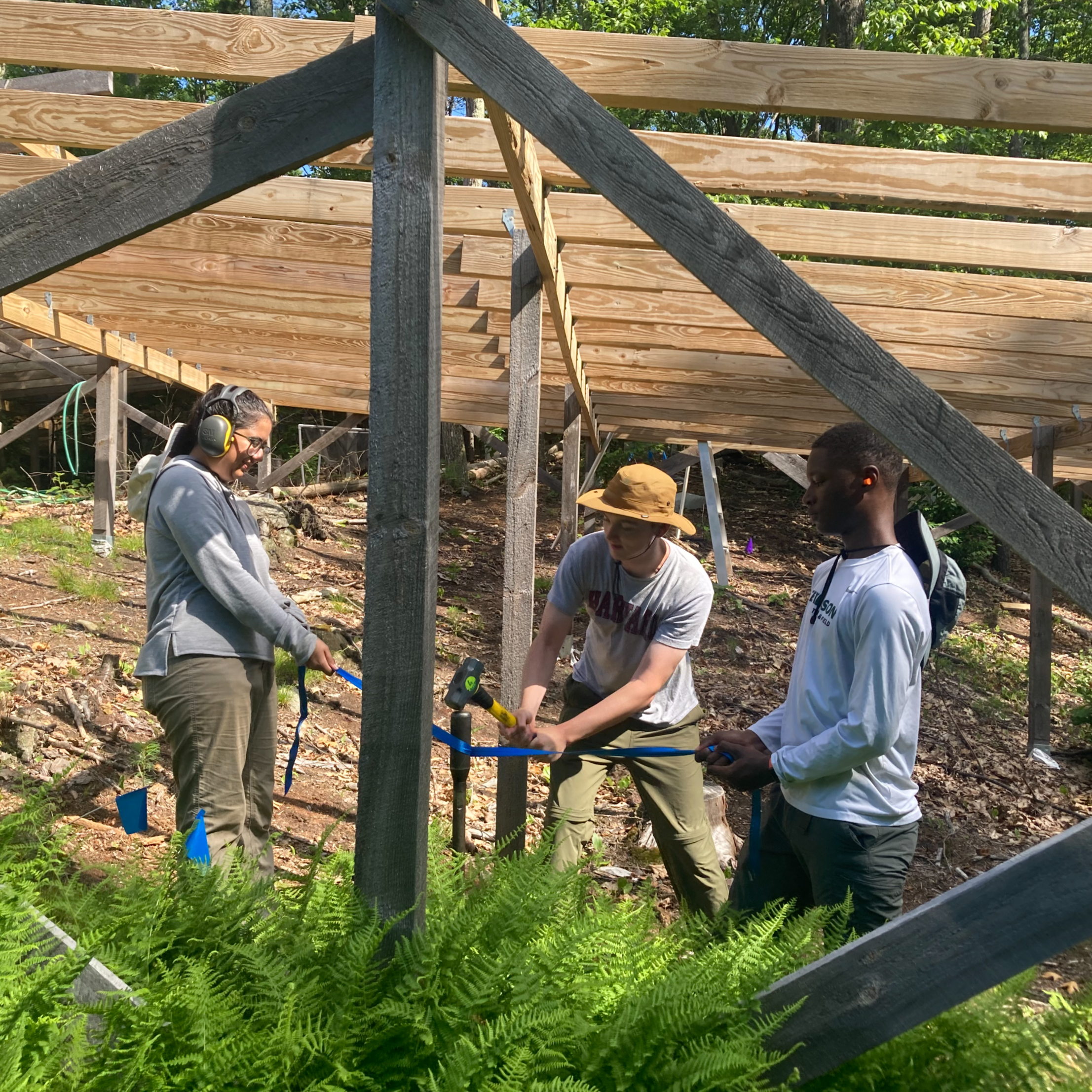
REU students demonstrate the hammering technique with strap.
Note
WARNING: Hammering puts increased strain on the core and may lead to core damage, particularly to the threads and cutting edge. To minimize breakage, a wrapped strap may be used to consistently tighten the the extension head onto the extension pole and safely maintain vertical alignment. The coring tip will need to be more frequently sharpened. Additionally, the cap of the core may be permanently welded onto the core itself.
Coring
Position the post driver directly above the core and drill with downwards pressure, ensuring that the red hammer sleeve stays positioned. It is difficult to see which way the core is traveling while drilling, so a spotter is helpful to ensure that the core travels straight downwards.
A. If the post driver continues downwards, continue drilling until reaching the marked 30 cm line. Continue to Step 8 but Skip Step 9.
OR
B. If the core stops moving downwards before reaching 30 cm, continue drilling for 30 seconds then switch to hammering.
AND
C. If hammering is unable to move the core downwards. Continue to Step 8 and Step 9.
Coring with post driver.
Coring
Remove the core from the borehole.
i. To prevent backfilling, briefly lift the wooden template and clear soil from around the core. Replace wooden template.
ii. Wiggle the core around to widen the hole.
iii. Remove the core manually or with a jack lift. Have a spotter hold the jack straight and/or make sure that the core is being pulled vertically.
iv. Brush off soil from the top and sides of the metal core.
v. Lay the core in a bin to avoid soil loss.
AMS Bigfoot Jack in action. We do not advise getting a core stuck with the extension pole higher than the maximum jack height.
Once the blocked core is removed, use the metal probe to determine what stopped the post driver.
If it is:
A. Rock: Use a chisel to break the rock fragments and incorporate that in the next increment. Continue with the core (Step 7). If the rock cannot be broken, record observations and end this core. If it is before 10cm, disregard this core and return to Step 2.
B. Root: Remove the pole driver. Use a sledgehammer to pound the core through the root. If unsuccessful, clippers or a saw can be used. Remove the piece and incorporate it with the next increment.
OR
C. Bedrock, regolith, groundwater, other immovable object: Record observations and end the core.
Measure the depth of the bore hole from the soil surface to the bottom of the hole.
Note
This number should determine the number of increments in Step 12.
Subsecting Core
Remove the liner from the metal core.
i. Unscrew cutting edge from metal core.
ii. Pull the core out.
iii. Place the liner cap over the liner opening until ready for Step 12.
With soil in the liner, measure increments and begin to push out the relevant increment of soil from the liner using a wooden dowel.
Note
0-30 cm: 5 cm increments
Below 30 cm: 10 cm increments
Some increments may be split between rounds of coring.
Using a knife and pruners when necessary, slice each increment as it is pushed out of the liner, and bag in a quart-sized plastic bag.
Label: Core ID, increment, date.
Store increments in cooler. Freeze as soon as possible.
Repeat Steps 6 – 14 until unable to core deeper.
Other Analysis Collection (Optional)
Using a smaller 2 inch diameter corer with a slide hammer attachment, core nearby (~20 cm) away from the large core hole. Sample increments until reaching the depth of the nearby large core hole achieved (note 20 cm increments at depths >30 cm):
0-10 cm
10-20 cm
20-30 cm
30-50 cm
50-70 cm
...
Note
Skip incomplete increments.
Store in plastic bag and shake to homogenize. Label: Core ID, Other Analysis, increment, date.
Place in cooler. Freeze as soon as possible.
Final Steps
Place orange driveway stakes to mark the perimeter of core.
Fill the core with 2 mm sieved soil from nearby clearing.
Using the Tumber Lumber to sieve soil.
Data Recording
For each core, record:
Date. Weather. Core coordinates. Debris cleared from coring area. Surrounding trees, shrubs, and other plants. Depth of organic–mineral soil horizon. Maximum core depth. Any other pertinent information.