Jul 25, 2025
Simple and replicable Clinostat build guide for simulation of microgravity
- Hugh Watson1,
- Douglas Bair2,
- Jens Hauslage3,
- Janine Oldfield1,
- Ian Cullen2,
- Jordan Witchard2,
- Frazer Thorpe2,
- Kim Johnson2,
- Doug Brumley1,
- Michelle Watt1
- 1University of Melbourne, Parkville, Australia;
- 2La Trobe University, Bundoora, Australia;
- 3German Aerospace Center (DLR), Cologne, Germany
- Clinostat build guide


Protocol Citation: Hugh Watson, Douglas Bair, Jens Hauslage, Janine Oldfield, Ian Cullen, Jordan Witchard, Frazer Thorpe, Kim Johnson, Doug Brumley, Michelle Watt 2025. Simple and replicable Clinostat build guide for simulation of microgravity. protocols.io https://dx.doi.org/10.17504/protocols.io.5jyl8q348l2w/v1
License: This is an open access protocol distributed under the terms of the Creative Commons Attribution License, which permits unrestricted use, distribution, and reproduction in any medium, provided the original author and source are credited
Protocol status: Working
We use this protocol and it's working
Created: June 26, 2025
Last Modified: July 25, 2025
Protocol Integer ID: 221152
Keywords: microgravity; clinostat; Space biology; gravity, simulation of microgravity clinostat, microgravity clinostat, applications for clinostat, clinostat machine, simulating microgravity, microgravity for plant growth experiment, microgravity, replicable clinostat, clinostat, clino, gravity load, gravity, perception of gravity, gravitational effect, mechanisms of graviperception, specific experiment, gravity vector, mechanism, graviperception, object rotate, simulation, physics, plant growth experiment, orbit
Funders Acknowledgements:
Australian Research Council
Grant ID: CE230100015
Disclaimer
CC-BY License applies
Abstract
Clinostats offer a cheap and efficient means of testing biological materials in conditions of microgravity similar to that experienced in Earth’s orbit and deep space. The mechanisms of graviperception in many organisms can be manipulated by a clinostat machine to cancel gravitational effects. Clino (tilting) stat (constant) operate by rotating an object around an axis perpendicular to the direction of gravity. This nullifies the perception of gravity by reorienting an enclosed object’s gravity vector or direction (Kim et al, 2023). As the object rotates, gravity is experienced by the object in all directions and, with time, the gravity load reduces close to 0 (Kim et al, 2023).
These instructions are for building a clinostat that can hold a petri-dish and is intended to be used for simulating microgravity for plant growth experiments. Basic electronic soldering skills, access to a 3D printer, and Arduino familiarity as well as some specialized equipment are needed to complete this build. Applications for clinostats include as student-led projects in schools, aligned with science, technology, engineering and math (STEM) curriculum to promote proficiencies in biology, physics, mechanics, electronics, and programming. Specific experiments using the clinostat require further material and are outlined in separate experiment material and methods resources (Hauslage et al, 2017; Nie et al, 2025; Unoosa, 2013).
Image Attribution
Douglas Bair
Guidelines
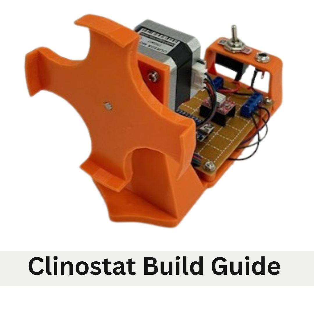
A clinostat is a research tool that is used to rotate a plant on a horizontal axis to conduct growth studies. This clinostat is designed to use 90mm petri dishes as the growth container. Other growth containers can be used but will require customization to the clinostat. This clinostat is composed of the 1. plate mount, 2. motor, 3. clinostat frame, 4. control unit circuit board, and 5. power terminal.
Materials
Tools and Equipment:
- 1x A4988 motor driver
- 1x 12v 55mA 2.1mm DC power
- 3D Printer adaptor
- Phillips head screwdriver
- 1x 4.7uF capacitor
- Needle nose pliers
- 3x2 pin PCB screw terminal 2.54mm pitch
- Soldering iron
- Wire cutter
- Tweezers
- Multi meter
- Male USB male mini B adaptor cable
- 3 hand PCB holder
- Solder wick
- 1x SPST toggle switch
- 1x 2.1mm DC bulkhead
- 1x25 x 30 experimenters board
3D Printed Parts:
- Clinostat frame
- Clinostat plate mount
Parts:
- Arduino Nano
- NEMA17 stepper motor with connection cables
- 4x M3 10mm Bolts
- 4x M3 bolt 15mm
- 4x M3 nut
- 8x M3 washer
Resources:
- Parts schematic
- Wiring diagram
- 3D Print files
- Arduino Script
Additional Resources:
- Soldering tutorial
- Multi meter How To: How to Use a Multimeter
Safety warnings
Soldering irons are very hot and should be treated with extreme caution as they can cause burns. Wear safety glasses and appropriate protective clothing.
GENERAL SOLDERING SAFETY NOTES
1. Never touch the element or tip of the soldering iron. They are very hot (about 400°C) and will burn.
The solder itself also gets hot.
2. Hold wires to be heated with tweezers or clamps.
3. Keep the cleaning sponge wet during use.
4. Always return the soldering iron to its stand when not in use. Never put it down on your
workbench. Be sure that the stand is weighted enough or attached to your worktable so that it
doesn’t topple over if you brush against the cord.
5. Turn unit off or unplug it when not in use.
6. Soldering irons come in models that use different wattages. Use the right size soldering iron for
your projects; too much heat can ruin your board or components.
7. Never, ever try to catch a hot soldering iron if you drop it. Let it fall, buy a new one if you have to
— just don’t grab it!
8. Give any soldered surface a minute or two to cool down before you touch it.
9. Always wash your hands with soap and water after soldering
3D Printing
3D Print the provided files to produce the Clinostat frame and the Plate mount. It is recommended that these parts are printed at a layer height not exceeding 2.0 mm. Refer to the instruction of the 3D printer being used for specific file preparations. After printing, remove print supports and debur bolt holes.
Control Unit
The control unit has two main parts the circuit board and the power terminal. Below are recommended practices and equipment to assist in assembling the circuit board and power terminal.
• Good quality soldering iron that maintains temperature
• Wet sponge for cleaning soldering iron tip
• Solder sucker or solder wick
• PCB third hand
• Ensure work area is well lit
• Use magnifying stand is available
• Organise parts for each step prior to building
• Double check wiring before powering up device
• Tin wires before soldering
The following instructions outline the recommended steps for assembly and order of operations. The location of the components on the circuit board is a suggestion and can be moved depending on personal preference. Placement location is cited using an X/Y grid reference where the X axis is a denoted by letters and Y axis is number.
When assembling the circuit board refer to the step-by-step instruction, the parts reference chart Appendix A, the component placement diagram Appendix B and the wiring diagram Appendix C.
Soldering Headers, Terminals and Capacitor
Solder the following components onto the circuit board and refer to Appendix B.
Arduino 15-pin female header: Solder 15-pin female headers in the footprint of an Arduino NANO. One 15-pin female header from (D,23) to (R,23). One 15-pin female header from (D,29) to (R,29).
A4988 stepper driver 8-pin female headers: Solder the 8-pin female headers in the footprint of an A4988 stepper driver. Solder one 8-pin female header from (M,11) to (1,11). Solder one 8-pin female header from (M,16) to (1,16).
Power connection 2-pin PCB Screw Terminal: Solder one 2-pin PBC screw terminal at (J,2) to (J,4). Orient terminal so the wire insert openings are pointed to the right. Label (J,2) pin of the terminal and circuit board as ground (GRD or -) and (J,4) side of the terminal as positive (+).
Soldering the 47uF Capacitor Terminal: Insert the 47uF capacitor into (F,2) and (F,4). Ensure the (-) pin is inserted into (F,2) and (+) pin is in (F,4). Bend the pins to the GRD / - pin and + pin of the 2-pin PCB screw terminal. Trim to length and solder to the 2-pin PCB screw terminal pins.
Stepper motor connection 4–pin PCN Screw: Solder the 4-pin PCB screw terminal (for motor connections) from (W,2) to (W8). Orient header so that the terminal openings are pointed outwards.
Wiring the Circuit
Solder the below connections using hook up wire that has been cut to length and the ends have been stripped and tinned. Multiple colors of wire are used to keep polarity and connections organized and to aid in troubleshooting. Use the wiring diagram Appendix C.
Power connections: Connect one red wire from + pin of the 2-pin PCB screw terminal (J,4) to NANO VIN (D,23). Connect one red wire from + pin of the 2-pin PCB screw terminal (J,4) to A4988 VMOT (M,11).
Connect one Black wire from the GND pin of the 2-pin PCB screw terminal (J,2) to NANO GND (E,23). Connect one Black wire from the GND PCB Screw Terminal (J,2) to A4988 GND (N,11).
Logic connections: Connect one Orange wire from NANO 5V (G,23) to A4988 MS1 (N,16). Bridge A4988 MS1 (N,16), MS2 (O,16), MS3 (P,16) together with a solder bead. Connect one Orange wire from A4988 MS3 (P,16) to A4988 VDD (S,11).
Connect one Black wire from NANO GND (G,29) to A4988 GND (T,11). Bridge A4988 RST (Q,16) and A4988 SLEEP (R,16) with a bead of solder. Connect one Blue wire from NANO AO (P,23) to A4988 STEP (S,16).
Motor connections
Connect the motor controls to the 4-pin PCB screw terminal.
Connect one Red wire from A4988 B2 (O,11) to 4-pin PCB screw terminal (W,2).
Connect one Blue wire from A4988 A2 (P,11) to 4-pin PCB screw terminal (W,4).
Connect one Green wire from A4988 A1 (Q,11) to 4-pin PCB Screw terminal (W,6).
Connect one Black wire from A4988 B1 (R,11) to 4-pin PCB Screw terminal (W,8).
Power Terminal
DC bulkhead jack and Toggle switch
Solder one end of a 3 cm length of prepared Red wire to the positive tip terminal of the 2.1mm DC bulkhead jack. Protect solder joint with a piece of 3mm heat shrink.
Thread a piece of 5mm heat shrink onto Red wire attached to 2.1mm DC bulkhead jack. Solder the free end of Red wire to one terminal of the SPST toggle switch. Protect solder joint with the 5mm piece of heat shrink.
Solder one end of a 4 cm length of prepared black wire to the negative sleeve terminal of the 2.1mm DC bulkhead jack. Protect solder joint with a piece of 3mm heat shrink.
Solder one end of a 4 cm length of prepared red wire to the wire-free terminal of the SPST toggle switch. Protect solder joint with a piece of 5mm heat shrink.
Clinostat Assembly
Circuit Board and power terminal installation
Place the circuit board on the clinostat frame with the 2-pin PCB Screw terminal side of the board being closest to the bridge. Secure it with M3 nuts and 15mm bolts.
Anchor the toggle switch and DC bulkhead assembly into the raised bridge on the clinostat frame. Secure using the threaded nuts included on each component.
Insert the + (red) wire from the toggle switch into the + side of the PCB pin screw terminal and secure. Insert the - (black) wire from the 2.1mm DC bulkhead into the GRD side of the PCB pin screw terminal and secure.
Stepper Motor Installation
Start by referring to the stepper motor’s product data sheet, which is often available for download from the retailer’s website. This will indicate which wire in the motor’s harness corresponds to each motor coil and phase. Use this information to correctly connect the motor to the 4-pin PCB screw terminal. Record the coil connections, polarities, and corresponding wire colors in the provided matrix, using the motor data sheet as a reference.
Mount the Stepper Motor onto the clinostat frame using four 10 mm bolts and 2 washers per bolt. Connect the supplied 4 wire cable to the stepper motor.
Trim, strip and tin Stepper motor cables so that they reach the 4 Pin PCN Screw Terminal on the circuit board with some slack (~15 cm). Using the wiring matrix completed in step 11.1 connect the motor wires to the appropriate terminal in the 4-Pin PCB Screw Terminal.
Press the 3D printed Plate Mount onto the motor axel so that the axel end is flush with the plate. The hole for the axel may need to be cleaned so that the axel fits. Be aware not to enlarge the hole as this is a friction fit.
Arduino Set-up and Programming
Arduino Set-up
Download the provided Clinostat Script. Connect Arduino to a computer using USB cable. Open Clinostat Script. In Tools menu select: Board: Arduino Nano, Processor: Almega3280, Port: COM_#.
Select the Library Manager. In Library Manager Search for “Accelstepper”. Install AccelStepper.
The rate of rotation of the clinostat plate can be adjusted in the script by changing the “Rotational Frequency”. This is measured in rotation per minute (RPM).
Upload Script to Arduino button by pushing upload button.
Final Assembly
Install the Arduino and the A4988 driver onto the clinostat control unit by gently pressing each component into the headers. Refer to the component position diagram (Appendix B) to orient the Arduino and driver in the correct position. Attach provided heat sink to Driver Chip. The clinostat is now complete and can be connected to power using the 12 AC Power adapter. Use rubber bands or hook and loop tape to secure growth plates to the plate mount when conducting experiments.
Protocol references
Hauslage J, Cevik V, Hemmersbach R (2017). Pyrocystis noctiluca represents an excellent bioassay for shear forces induced in ground-based microgravity simulators (clinostat and random positioning machine). npj Microgravity. 3:12. doi: 10.1038/s41526-017-0016-x
United Nations Programme on Space Applications (2013). Teacher’s Guide to Plant Experiments in Microgravity. Human Space Technology Initiative.
Nie H., Zhou W., Zheng Z., Deng Y., Zhang W., Zhang M., Jiang Z., Zheng H., Yuan L., Yang J., and Wang H.
(2025). Exploring plant responses to altered gravity for advancing space agriculture. Plant Comm. 6, 101370.
https://doi.org/10.1016/j.xplc.2025.101370
Kim, D., Nguyen, Q.T.T., Lee,S. et al. Customized small-sized clinostat using 3D printing and gas-permeable polydimethylsiloxane culture dish. npj Microgravity 9, 63 (2023). https://doi.org/10.1038/s41526-023-00311-1