Sep 08, 2025
REVA #6: 3D Tracing of Cadaveric Human Vagus Nerves
- Noa B Nuzov1,
- Valerie Lam1,
- Nicole A Pelot2,
- Andrew R. Crofton3,4,
- Andrew J. Shoffstall1,5
- 1Department of Biomedical Engineering, Case Western Reserve University, Cleveland, OH, USA, 44106;
- 2Department of Biomedical Engineering, Duke University, Durham, NC, USA, 27708;
- 3Department of Anatomy, Case Western Reserve University, Cleveland, OH;
- 4Department of Pathology and Cell Biology, University of South Florida, Tampa, FL;
- 5APT Center, Louis Stokes Cleveland Department of Veterans Affairs Medical Center, Cleveland, OH
- Noa B Nuzov: ORCID: 0000-0001-8187-2115;
- Valerie Lam: ORCID: 0009-0005-6777-3184;
- Nicole A Pelot: ORCID: 0000-0003-2844-0190;
- Andrew R. Crofton: ORCID: 0000-0002-1105-3971;
- Andrew J. Shoffstall: ORCID: 0000-0002-0881-2180


Protocol Citation: Noa B Nuzov, Valerie Lam, Nicole A Pelot, Andrew R. Crofton, Andrew J. Shoffstall 2025. REVA #6: 3D Tracing of Cadaveric Human Vagus Nerves. protocols.io https://dx.doi.org/10.17504/protocols.io.dm6gpm98pgzp/v1
Manuscript citation:
License: This is an open access protocol distributed under the terms of the Creative Commons Attribution License, which permits unrestricted use, distribution, and reproduction in any medium, provided the original author and source are credited
Protocol status: Working
We use this protocol and it's working
Created: July 15, 2025
Last Modified: September 08, 2025
Protocol Integer ID: 225837
Keywords: Human anatomy, Gross anatomy, Vagus nerve, Cranial nerves, Peripheral nervous system, Autonomic nervous system, Neuroanatomy , 3d tracing of cadaveric human vagus nerve, cadaveric human vagus nerves this protocol detail, xyz coordinates of the vagus nerve, cadaveric human vagus nerves this protocol, 3d tracing, cadaveric human vagus nerve, human cadaver, vagus nerve, embalmed human cadaver, optical tracker system, cadaver, gross anatomical context, points cloud, xyz coordinate, nerve, specific coordinate location
Funders Acknowledgements:
NIH SPARC REVA
Grant ID: 75N98022C00018
Disclaimer
DISCLAIMER – FOR INFORMATIONAL PURPOSES ONLY; USE AT YOUR OWN RISK
The protocol content here is for informational purposes only and does not constitute legal, medical, clinical, or safety advice, or otherwise; content added to protocols.io is not peer reviewed and may not have undergone a formal approval of any kind. Information presented in this protocol should not substitute for independent professional judgment, advice, diagnosis, or treatment. Any action you take or refrain from taking using or relying upon the information presented here is strictly at your own risk. You agree that neither the Company nor any of the authors, contributors, administrators, or anyone else associated with protocols.io, can be held responsible for your use of the information contained in or linked to this protocol or any of our Sites/Apps and Services.
Abstract
This protocol details the process to digitize the xyz coordinates of the vagus nerve and its branches in situ, dissected in an embalmed human cadaver, with gross anatomical context, using the Northern Digital (NDI) optical tracker system. We acquired two types of data: points clouds used to approximate one specific coordinate location and continuous curves to represent a path.
Attachments

Image Attribution
Photo taken by Noa Nuzov. The stylus pictured is sold by Northern Digital (NDI).
Materials
1. NDI Optical Tracking System (Link here: https://www.ndigital.com/optical-measurement-technology/optical-measurement-products/)
- Model: Polaris Vega ST
- Includes the camera/sensor only, power cord, and Ethernet cables.
2. NDI Tracking software. Go to NDI Customer Support (https://support.ndigital.com/s/) to make an account to download the software.
- Download the most up-to-date ToolBox program (e.g., ToolBox 6.001.027 for Windows (64-bit)).
- Download the software to a computer that can interface with the Ethernet cables or use an Ethernet-to-USB port adapter.
3. NDI Passive 4-marker probe. (Link here: https://www.ndigital.com/optical-measurement-technology/polaris-tools-and-accessories/)
- This is included with the NDI optical tracking system purchase, but can also be bought separately.
- To create a better grip, a rubber band can be wrapped around the stylus.
4. NDI passive marker spheres. (Link here: https://www.ndigital.com/optical-measurement-technology/passive-marker-spheres/)
- These often come with the NDI optical tracking system; however, if all spheres are damaged, additional spheres can be purchased.
5. Tripod for the camera (Link here: https://www.amazon.com/MACTREM-Magnesium-Portable-Samsung-Cameras/dp/B00L4RMRMM).
- Brand: Mactrem, sold by Amazon. Height: 84 inches. Includes a ball head and level.
6. Calibration block. This was custom 3D modeled and printed for this project. However, any block with a cone-shaped divot in it at least 3-5 mm deep will suffice.
7. A piece of paper that has been laminated or any large flat object that blocks light.
Safety warnings
This protocol might include items and/or substances that may pose hazards (e.g., chemical, physical, biological, or otherwise) to your health upon use or exposure. Before engaging in the processes described in this protocol, familiarize yourself with and follow the safety data sheets, manufacturer safety recommendations, and local regulations.
Ethics statement
Be sure to seek approval for or an exemption from human subjects research from your local regulatory body(ies) as required by local and/or institutional regulations before initiating studies.
This study was determined to be exempt from IRB oversight by the Case Western Reserve University Institutional Review Board (IRB) because it involved de-identified cadaveric tissue and no protected health information was collected from the donors.
Before start
See the protocol for dissecting the human vagus nerve from embalmed cadavers (dx.doi.org/10.17504/protocols.io.yxmvmb976g3p/v1).
Section 1: Nerve Tracing Data Collection
After dissection, the data to be traced are:
The vagus nerve and branches.
Other nearby nerves and their branches.
Standardized gross anatomical “landmarks” (Appendix 1).
Standardized points of relevance on the trunk of the vagus nerve (termed anatomical “levels”) that are in the same horizontal plane as chosen landmarks (Appendix 1, Table 2 in dx.doi.org/10.17504/protocols.io.yxmvmb976g3p/v1).
Ensure the cadaver is in a position where it does not need to be moved to physically access all desired anatomy with the 3D tracker stylus.
Set up the NDI sensor on the tripod. Plug in the power cord and all cables connecting the sensor to the computer (Figure 1).
Figure 1: NDI sensor on the tripod.
Align the long z-axis of the sensor with the superior-inferior axis of the cadaver (Figure 2).
Figure 2: Global coordinate frame of the NDI sensor from the NDI support manual
Both the camera’s tripod and the surface on which the cadaver is placed must be locked and well secured to minimize movement.
If the tripod has a built-in level, use it to ensure the camera is level relative to the ground.
It is recommended to have one operator using the software on the computer while another person performs the tracing with the stylus. Henceforth, the former is referred to as the “computer operator” and the latter is referred to as the “tracer”.
Open the most up-to-date “NDI Track” software on the computer connected to the sensor. Connect to the sensor.
Once the sensor is detected by the software, the software will show the pyramidal volume and the stylus in space as shown in Figure 3.
Figure 3: (1) Infrared light emitted. Passive sphere markers reflect the light to the sensors. (2) After calibration, the tracking software tracks the position of the tip of the stylus relative to passive sphere markers. (3) The location of the tip of the stylus is shown from three views on the NDI Track software. (4) The X, Y, and Z coordinates and the rotation of the stylus collected from NDI Track software.
Ensure that the sensor can detect the stylus in the area of desired tracing. Physically adjust the position of the sensor so that all target areas are captured in the field of view.
Calibrate the sensor using the calibration block with the cone-shaped divot that is 4 mm deep. This will allow the sensor to track the tip of the stylus relative to the spheres.
If there is a previous calibration, remove it by selecting “File” and “Remove Tip Offset”.
Place the calibration block on a flat surface, such as a table, and securely tape it down to ensure that it will not move.
Place the stylus tip vertically in the divot.
Begin the calibration process by selecting “File” and “Pivot Tool”. Choose a start delay, such as 2-3 seconds, and a duration of at least 30 seconds.
Once the calibration process begins, rotate the stylus in slow circles, with the stylus tip remaining in the divot. The stylus should be rotating at an angle of about 45°, minimum 30°, to prevent an error.
If the calibration is successful, press “Apply Offset”.
Ensure the tracing is in “Euler Angle Format” under the “View” tab, and the “Volumes” is “Pyramid” and the frame rate is set to “60” under the “Track” tab.
3D nerve tracing data are saved as CSV files and are collected in two ways:
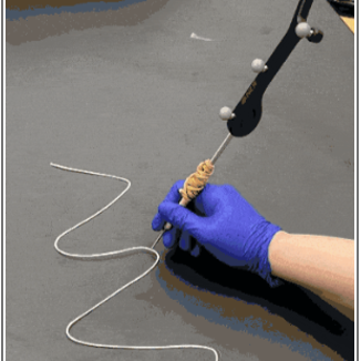
Continuous data: The 3D tracker stylus is moved along the paths of target nerves or structures. This “continuous” data collection is used for tracing the center of the vagus nerve, the other nerves, and branches of the vagus and other nerves (Figure 4). Assuming the sampling interval is set to zero, the default frequency of the device is 60 Hz after Step 9, so 60 points are collected per second.
Figure 4: Photo of researcher using the stylus to trace anatomy using the NDI system sensor, seen in the background
Point data: The 3D tracker stylus is used to “point” at specific physical locations in space. An object is used to physically block the sensor in between desired points to create stoppages in the data. This “point” data collection is used for collecting data on “points” in space, such as the non-nerve anatomical “landmarks” and relevant points on the vagus main trunk referred to as “levels”. The true data collected are a point cloud, so the centroid of the point cloud should be used to approximate the point location.
When collecting data, the computer operator must watch the NDI Track software to make sure no interference occurs during data collection.
“Interference” error will appear if other objects or light in the room are affecting the sensor’s ability to locate the passive sphere markers.
There are four passive sphere markers labeled A, B, C, and D on the stylus (Figure 3). When visible, they will appear green in the software; if not visible, the letter of the blocked sphere will appear red, and an error will appear.
If an error occurs during data collection, select “Close” and try again. If the new file has the same name, a prompt will appear to override the original file.
Instructions for collecting “continuous” data:
In the NDI track software, choose: “File” and “Record data”.
Name the file appropriately and select the correct location on your computer to save.
Select the output file type as “Comma-Separated Values (.csv)”.
Set the start delay to 00:00:02 -00:00:03 to account for pointing at the first location with the stylus tool.
Set the record duration time for the data collection. This can be set to a very large number (e.g., 50,000 seconds) since data collection can be ended when desired.
Set the sampling interval to zero (0), which will collect the maximum number of points possible per second using the default 60 Hz frequency of the device (and confirmed in Step 9). If another frequency is desired, the computer operator can control this by entering a “sampling interval”, which is the time in seconds between collected data points.
Click “Start recording” and move the stylus slowly along the surface to trace.
When tracing continuously, specify in notes the direction of the tracing (e.g., superior to inferior, medial to lateral, etc.) such that the order of points in the output data is anatomically relevant. For branches of nerves, it is recommended to start the tracing at the branch point so that directionality in the data is preserved. Then the first point of the output data represents the location where the branch exits the main trunk of the nerve.
Once data collection is complete for a file, the computer operator can click “Close” on the screen, and it will end data collection. You do not need to wait until the time duration has ended for a file.
Instructions for collecting “point” data:
In the NDI track software, choose: “File” and “Record data”.
Name the file appropriately and select the correct location on your computer to save.
Select the output file type as “Comma-Separated Values (.csv)”.
Set the start delay to 00:00:02 -00:00:03 to account for pointing at the first location with the stylus tool.
Set the record duration time for the data collection. This can be set to a very large number (e.g., 50,000 seconds) since data collection can be ended when desired.
Set the sampling interval to zero (0), which will collect the maximum number of points possible per second using the default 60 Hz frequency of the device (and confirmed in Step 9).
Click “Start recording” and point with the nerve tracing stylus to all point data that will be collected in a single file. When moving the stylus between points, use a piece of paper to block the sensor. You can block either of the two black sensors on the sides of the NDI Polaris Vega system. The computer operator will be able to see when blockages are occurring as a red error will appear on the NDI software screen in real time.
Once data collection is complete for a file, the computer operator can click “Close” on the screen, and it will end data collection. You do not need to wait until the time duration has ended for a file.
When looking at the output data for data that had blockages, points that were blocked will have an error listed in the “State” column. Only points that are not blocked will have “OK” in the “State” column. Code can be used to later separate the data where blocking errors are generated.
If manual separation of the data later is not desired, the computer operator can make a new file for each point cloud. Click “Start recording” and point with the nerve tracing stylus to the desired point in space. After allowing a few seconds to pass, the computer operator can click “OK” on the screen to end data collection. The centroid of the point cloud can be used to approximate the physical point in space.
If the generation of a point cloud is not desired, the computer operator can make a file that contains a single point in space by specifying the sampling interval to “2” seconds and then setting the record duration to “1” second. This means only a single point is acquired within the duration window.
Once data have been collected, it is recommended to collect a control dataset where the tracer points at a single location for 00:00:20 -00:00:30 and tries not to move their hand. The distribution of points in space can be used to estimate the degree of error of the tracer due to normal hand tremor.
Section 2: Superficial Cervical Nerves Tracing Data Collection
Follow the steps in Section 1 to set up the tracing system and understand the methods of tracing.
After the body has undergone superficial cervical dissection, nerves that are superficial to the sternocleidomastoid muscle (SCM) will be available as well as the nerves directly underneath the SCM (e.g., the ansa cervicalis).
The data to be traced are:
Nerves in the cervical area that are superficial to the SCM or directly posterior to it, and their branches.
Standardized gross anatomical “landmarks”.
Using the method for collecting “point” data, collect data by pointing at each desired anatomical landmark with the tip of the stylus.
Use the method for collecting “continuous” data to trace the center along each nerve above the SCM.
Collect a separate file for each nerve.
Collect a separate file for each branch of the nerve(s).
Reflect the SCM laterally. Use the method for collecting “continuous” data to trace each nerve that is immediately posterior to the SCM.
Acknowledgements
The authors thank the donors and staff of the Case Western Reserve University Anatomical Gift Program. Without the selfless donations of the donors and the tireless efforts of the staff of this program, the methods described in this protocol and the insights and advancements that result from studies conducted according to this protocol would not be possible.