Aug 19, 2025
Pudendal Nerve Mapping in Humans
- Amador Lagunas1,2,
- Po-Ju Chen1,2,
- Priyanka Gupta3,
- Tim Bruns1,2
- 1Department of Biomedical Engineering, University of Michigan, Ann Arbor, MI;
- 2Biointerfaces institute, University of Michigan, Ann Arbor, MI;
- 3Department of Urology, University of Michigan, Ann Arbor, MI
- SPARCTech. support email: [email protected]


Protocol Citation: Amador Lagunas, Po-Ju Chen, Priyanka Gupta, Tim Bruns 2025. Pudendal Nerve Mapping in Humans. protocols.io https://dx.doi.org/10.17504/protocols.io.14egn3jezl5d/v1
Manuscript citation:
Chen P, Lagunas AC, Soriano V, Gupta P, Bruns TM. Perineal and Rectal Nerve Recruitment Order Varies During Pudendal Neurostimulator Implant Surgery. Neurourology and Urodynamics. 2025;44(4):851-859. doi:10.1002/nau.70010
Lagunas AC, Chen PJ, Ruiz L, et al. Factors Affecting Anal Sphincter Recruitment During Intraoperative Pudendal Nerve Stimulation: An Observational Study. International Urogynecology Journal. Published online 2025. doi:10.1007/s00192-025-06238-3
License: This is an open access protocol distributed under the terms of the Creative Commons Attribution License, which permits unrestricted use, distribution, and reproduction in any medium, provided the original author and source are credited
Protocol status: Working
We use this protocol and it's working
Created: November 21, 2023
Last Modified: August 19, 2025
Protocol Integer ID: 91299
Keywords: pudendal, human, lower urinary tract, urethra to different pudendal nerve stimulation frequency, pudendal nerve mapping in human, pudendal nerve mapping, different pudendal nerve stimulation frequency, pudendal nerve with imaging, pudendal nerve, pelvic anatomy, response of the bladder, stimulation parameter, pelvic health, lower urinary tract function, pelvic floor, bladder, implanted neurostimulator, ct scan, patient specific map, mri, electrophysiology, bladder state, patient specific maps of each participant, device implantation experimental trial, imaging, device implantation, neurostimulator as part, cystometrogram
Funders Acknowledgements:
NIH SPARC
Grant ID: OT2OD028191
Abstract
The goal of this study is to map the pudendal nerve with imaging and electrophysiology by gathering additional data from patients receiving an implanted neurostimulator as part of their normal clinical care, and to examine the response of the bladder and urethra to different pudendal nerve stimulation frequencies in humans. There are 5 main parts to this study. Participants complete pre and post study questionnaires to asses their pelvic health and functional change. Volumetric imaging with MRI and CT scans are done to create patient specific maps of each participant's pelvic anatomy. Additional details on the parameters used for the MRI and CT scans can be found here:dx.doi.org/10.17504/protocols.io.yxmvm978bl3p/v1. During device implantation experimental trials are performed in the OR to asses the impact of different simulation parameters on the pelvic floor. After device implantation experimental trials are performed during a cystometrogram to asses how bladder state and stimulation parameters affect pelvic floor and lower urinary tract function.
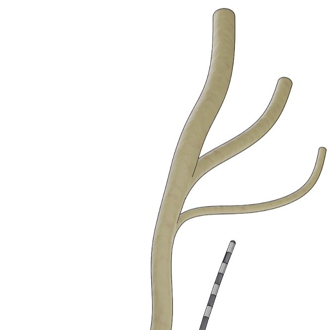
Image Attribution
Luis Ruiz
Materials
ManoScan ESO High Resolution Manometry System
High-resolution esophageal small diameter catheter, 7.5 mm spacing - MSC-3886
Cadwell reference jumpers
Cadwell Cascade Elite intraoperative neuromonitoring system
Laborie Urodynamics system
Air-charged Dual Sensor Catheter, Radiopaque (TDOC-7FDR, Laborie)
Neotrode II EMG patches (1741-003, ConMed Corporation)
3T MRI - Ingenia 3T system, Philips
CT Scanner - DiscoverCT750 HD or Revolution scanner, GE Healthcare
HR Lubricating Jelly
Pre-study surveys
Have participants complete American Urological Association Symptom Index (AUASI) [1]
Citation
LINK
, Michigan Incontinence Symptom Index (MICI)[2]
Citation
LINK
, Female Sexual Function Index short form (FSFI-6) for women [3]
Citation
LINK
or the International Index of Erectile Function (IEEF-5) men[4]
Citation
LINK
, Colorectal-Anal Distress Inventory 8, and Female GenitoUrinary Pain Index (FGUPI) for women[5]
Citation
LINK
or Male GenitoUrinary Pain Index (MGUPI) for men [6].
Citation
LINK
MR Imaging
Complete MR imaging of the pelvis. Imaging protocols enable pudendal nerve visualization and are described in dx.doi.org/10.17504/protocols.io.yxmvm978bl3p/v1.
Stage 1 Intraoperative Testing
Turn on Manoscan recording software and calibrate Manoscan high-resolution esophageal small diameter catheter per Manoscan manual guidelines.
Begin data recording session and change display so only channels in the bladder, bladder neck, and urethra are visible.
Add lubricating jelly to the tip of the Manoscan catheter and place catheter into the urethra until resistance is met and catheter cannot go any deeper.
Record the first visible sensor outside the body using the numbered label on the catheter.
Tape the catheter to the patients body so that it remains in place and does not change position or slide out.
Place electromyography (EMG) needles across the anal sphincter at the 3 and 9 o'clock position until the needle is no longer visible [7].
Citation
LINK
Connect the needle electrodes to Cadwell Cascade Elite intraoperative neuromonitoring system and begin recording with a sampling rate of 333 Hz.
After multicontact lead has been placed next to the pudendal nerve as described in Peters 2013, connect the external pulse generator to electrode 0 and a surface patch electrode placed on the ankle.
Change stimulation frequency of the external pulse generator to 3 Hz.
Change pulse width to 210 microseconds.
Increase stimulation amplitude until external anal sphincter contraction is detected by intraoperative nueromonitoring team on EMG readout then turn off stimulation.
Apply stimulation for 10 seconds then turn off stimulation.
Double previous stimulation amplitude and apply stimulation for 10 seconds.
Repeat step 9.2 until stimulation amplitude would be above 5 mA.
Change pulse width to 60 microseconds.
Repeat step 9 and all substeps.
Change pulse width to 450 microseconds.
Repeat step 9 and all substeps.
Connect to electrode 1.
Repeat steps 8-13.
Connect to electrode 2.
Repeat steps 8-13.
Connect to electrode 3.
Repeat steps 8-13.
Connect implanted lead to temporary pulse generator.
Set the electrode with the lowest external anal sphincter activation threshold as the cathode and set the electrode with the second lowest external anal sphincter activation threshold as the anode.
Repeat steps 8 and 9.
Set the electrode with the second lowest external anal sphincter activation threshold as the cathode and set the electrode with the lowest external anal sphincter activation threshold as the anode.
Repeat steps 8 and 9.
Set the electrode with the third lowest external anal sphincter activation threshold as the cathode and set the electrode with the lowest external anal sphincter activation threshold as the anode.
Repeat steps 8 and 9.
Set the electrode with the fourth lowest external anal sphincter activation threshold as the cathode and set the electrode with the lowest external anal sphincter activation threshold as the anode.
Repeat steps 8 and 9.
End of session. Save Manoscan recording data and close software. Remove catheter from participant. Collect anal sphincter EMG data from recording system for later analysis.
Cystometrogram Experimental Trials
Set up as described in steps 3 and 4.
Place urodynamics TDOT air charged catheter into the urethra and rectum. Place EMG patch electrode across the anus at the 3 and 9 o'clock position. Connect sensors to Laborie urodynamics system and begin recording.
Using the pudendal neurostimulator control software set the case as the anode and electrode 0 as the cathode. Determine the sensory threshold and maximum tolerable threshold at 14 Hz and 210 microsecond pulse width.
Determine the sensory threshold and maximum tolerable threshold for each of the remaining electrode with the case as the anode.
Fill the bladder until participant feels a strong urge to void.
Set stimulation frequency to 3 Hz, set electrode with lowest sensory threshold as the cathode, and set the case as the anode.
Increase stimulation amplitude until participant first senses stimulation. Remain at this amplitude for at least ten seconds.
Increase stimulation amplitude to participants maximum tolerable threshold. Remain at this amplitude for at least ten seconds. Then turn off stimulation.
Change stimulation frequency to 30 Hz.
Increase stimulation amplitude until participant first senses stimulation. Remain at this amplitude for at least ten seconds.
Increase stimulation amplitude to participants maximum tolerable threshold. Remain at this amplitude for at least ten seconds. Then turn off stimulation.
Set stimulation frequency to 3 Hz, set electrode with second lowest sensory threshold as the cathode, and set the case as the anode.
Increase stimulation amplitude until participant first senses stimulation. Remain at this amplitude for at least ten seconds.
Increase stimulation amplitude to participants maximum tolerable threshold. Remain at this amplitude for at least ten seconds. Then turn off stimulation.
Change stimulation frequency to 30 Hz.
Increase stimulation amplitude until participant first senses stimulation. Remain at this amplitude for at least ten seconds.
Increase stimulation amplitude to participants maximum tolerable threshold. Remain at this amplitude for at least ten seconds. Then turn off stimulation.
Set stimulation frequency to 3 Hz, set electrode with lowest sensory threshold as the cathode, and set the electrode with second lowest threshold as the anode.
Increase stimulation amplitude until participant first senses stimulation. Remain at this amplitude for at least ten seconds.
Increase stimulation amplitude to participants maximum tolerable threshold. Remain at this amplitude for at least ten seconds. Then turn off stimulation.
Change stimulation frequency to 30 Hz.
Increase stimulation amplitude until participant first senses stimulation. Remain at this amplitude for at least ten seconds.
Increase stimulation amplitude to participants maximum tolerable threshold. Remain at this amplitude for at least ten seconds.
Set stimulation frequency to 3 Hz, set electrode with lowest sensory threshold as the anode, and set the electrode with the second lowest sensory threshold as the cathode.
Increase stimulation amplitude until participant first senses stimulation. Remain at this amplitude for at least ten seconds.
Increase stimulation amplitude to participants maximum tolerable threshold. Remain at this amplitude for at least ten seconds.
Change stimulation frequency to 30 Hz.
Increase stimulation amplitude until participant first senses stimulation. Remain at this amplitude for at least ten seconds.
Increase stimulation amplitude to participants maximum tolerable threshold. Remain at this amplitude for at least ten seconds.
Change electrode combination to match what the participant uses for at home therapy.
Note
Participants should have an electrode configuration they use at home that gives the best relief of symptoms. This electrode configuration should be used for the next portion of testing
Increase stimulation amplitude until participant first senses stimulation. Remain at this amplitude for at least ten seconds.
Increase stimulation amplitude to participants maximum tolerable threshold. Remain at this amplitude for at least ten seconds.
Apply stimulation using at-home stimulation settings and with the at-home stimulation amplitude. Have the participant attempt to void with both catheters in the urethra.
Note
If the participants is unable to void with both catheters placed in the urethra remove the manoscan catheter and have the participant attempt to void again.
End of session. Save data from Manoscan and shut down software. Remove remaining catheters from the participant. Collect pressure and EMG data from the urodynamics system.
CT Imaging
Complete CT imaging of the pelvis after implantation of the device lead to that the lead location can be co-localized into a participants specific model of their pelvic anatomy.
Post Study Survey
Have participants complete the same surveys that were issued in step 1.
Protocol references
1. M. J. Barry et al., “The American Urological Association Symptom Index for Benign Prostatic Hyperplasia,” J. Urol., vol. 5, no. 1, pp. 1549–1557, 1992.
2. A. M. Suskind, R. L. Dunn, D. M. Morgan, J. O. L. DeLancey, E. J. McGuire, and J. T. Wei, “The Michigan Incontinence Symptom Index (M-ISI): A Clinical Measure for Type, Severity, and Bother Related to Urinary Incontinence,” Neurourol. Urodyn., vol. 33, pp. 1128–1134, 2014.
3. A. M. Isidori et al., “Development and validation of a 6-item version of the female sexual function index (FSFI) as a diagnostic tool for female sexual dysfunction,” J. Sex. Med., vol. 7, no. 3, pp. 1139–1146, 2010.
4. R. C. Rosen, J. C. Cappelleri, M. D. Smith, J. Lipsky, and B. M. Peñ, “Development and evaluation of an abridged, 5-item version of the International Index of Erectile Function (IIEF-5) as a diagnostic tool for erectile dysfunction,” Int. J. Impot. Res., vol. 11, no. 6, pp. 319–326, 1999.
5. M. D. Barber, M. D. Walters, and R. C. Bump, “Short forms of two condition-specific quality-of-life questionnaires for women with pelvic floor disorders (PFDI-20 and PFIQ-7),” Am. J. Obstet. Gynecol., vol. 193, no. 1, pp. 103–113, 2005.
6. J. Q. Clemens et al., “Ambulatory and Office Urology National Institutes of Health Chronic Genitourinary Pain in Both Men and Women,” Urology, vol. 74, no. 5, pp. 983–988, 2009.
7. Peters KM. Pudendal Neuromodulation for Sexual Dysfunction. The Journal of Sexual Medicine. 2013;10(4):908-911. doi:10.1111/jsm.12138