Apr 10, 2025
Production of The Aluminum Nitric-acid Keg (TANK) for mitigating explosions during the oxidation of black carbon into benzenepolycarboxylic acid (BPCA) molecular markers
- Madelyn Miller1,
- Alex Collins1,
- Riley Barton1,
- Morgan Schaller1,
- Sasha Wagner1
- 1Center for Environmental Stable Isotope Analysis & Department of Earth and Environmental Sciences, Rensselaer Polytechnic Institute, Troy, New York, USA


Protocol Citation: Madelyn Miller, Alex Collins, Riley Barton, Morgan Schaller, Sasha Wagner 2025. Production of The Aluminum Nitric-acid Keg (TANK) for mitigating explosions during the oxidation of black carbon into benzenepolycarboxylic acid (BPCA) molecular markers. protocols.io https://dx.doi.org/10.17504/protocols.io.eq2lynz4qvx9/v1
License: This is an open access protocol distributed under the terms of the Creative Commons Attribution License, which permits unrestricted use, distribution, and reproduction in any medium, provided the original author and source are credited
Protocol status: Working
We use this protocol and it's working.
Created: December 05, 2021
Last Modified: April 10, 2025
Protocol Integer ID: 55695
Keywords: black carbon, charcoal, oxidation, BPCA, nitric acid fume, black carbon into benzenepolycarboxylic acid, excess nitric acid into glass ampule, explosions during the oxidation, mitigating explosion, production of the aluminum nitric, excess nitric acid, acid keg, possible destruction of oxidation oven, aluminum nitric, oxidation oven, benzenepolycarboxylic acid, cascading explosion, flame sealing, explosion, molecular markers black carbon, black carbon, more consistent heating of sample, oxidation, such explosion, carbon, bpca molecular markers for subsequent separation
Disclaimer
This apparatus is not intended to stop ampules from exploding during oxidation. The job of TANK is to prevent a singular explosion from propagating to other ampules, thus eliminating the loss of surrounding samples.
CAD models for the recommended latches and handles were used with permission from McMaster-Carr®.
Abstract
Black carbon is often measured using the benzenepolycarboxylic acid (BPCA) method, where condensed aromatics are oxidized into BPCA molecular markers for subsequent separation and quantification via HPLC. The process involves placing sample and excess nitric acid into glass ampules, flame sealing, and heating (often between 150-180 ºC for multiple hours). During oxidation, pressure from within the ampule can cause it to explode, resulting in sample loss and possible destruction of oxidation ovens. Another issue that arises from such explosions is the "domino-effect" where when one sample explodes, it also destroys surrounding samples, exacerbating the aforementioned consequences. Here we provide schematics and instructions for the production of The Aluminum Nitric-acid Keg, or TANK. This apparatus was designed to isolate individual samples to stop the domino-effect, decreasing sample loss and in turn limit released nitric acid fumes. It should be noted, however, that despite the singular intention of preventing cascading explosions, employment of TANK has resulted in a dramatic decrease in our lab's explosions overall, possibly due to more consistent heating of samples.
For a step-by-step protocol describing the BPCA method, please see Barton and Wagner (2022) and the associated protocol here at protocols.io!


Guidelines
Feel free to optimize TANK to your personal needs. These instructions can be used to manufacture TANK yourself or to assist the staff at your institution's machine shop. If you do use TANK for your black carbon, or other, analyses, please cite this protocol.
Materials
The following parts and dimensions are based on the internal dimensions of our oxidation oven (HP 5890 Series II Gas Chromatograph) and DWK Life Sciences 20mL Prescored Clear Ampules (Mfr. No. 176782).
You should adjust dimensions as needed to accommodate your oven and ampule sizes.
- Aluminum Blocks
-Recommended from McMaster-Carr:
Multipurpose 6061 Aluminum 6" X 6", 1 ft. Long - Cat. No. 8975K335 (for the body)
Multipurpose 6061 Aluminum 1" X 6", 1 ft. Long - Cat. No. 9008K881 (for the lid)
*These may need to be cut down, as the length options are limited
- x2 3/8in diameter, 1.5-2" long metal rods (we used steel, but steel will corrode from nitric acid if an ampule bursts; consider aluminum alloys, 304 stainless steel, or 4% silicon stainless steel)
-Recommended from McMaster-Carr:
Multipurpose 304 Stainless Steel Rod, 3/8" Diameter, 1/2 ft. Long - Cat. No. 89535K871
*This recommendation will need to be cut to size
- x2 Folding chest handles and corresponding screws (screws no longer than 5/8")
-Recommended from McMaster-Carr:
Round Folding Pull Handle 304 Stainless Steel, 3-3/8" Wide - Cat. No. 1647A113 x2
316 Stainless Steel Pan Head Phillips Screws, 10-32, 1/2" Long - Cat. No. 91735A829
- x2 Latches and corresponding screws (no longer than 5/8")
-Recommended from McMaster-Carr:
Screw on Draw Latch, 304 Stainless Steel, 1-3/4" Long x 7/8" Wide - Cat. No. 6082A12 x2
316 Stainless Steel Pan Head Phillips Screws, No. 6, 7/16" Long - Cat. No. 91735A147
- Cutting fluid
-Recommended: Tap Magic ProTap
- Optional: Placement guides printed to scale (from the provided "Blueprint and Templates" PDF)
Equipment
- 1" drill bit – at minimum 6" long; meant for metal
- Set of smaller drill bits – at minimum 3/8", 7/16", and additional bits that correspond to the size of screws for handles and latches (#21 and #36 for the recommended screws)
- Tap and die set
- Drill press – with minimum 5.5" of spindle travel and adjustable speed
- 6" cross slide vise (heavy duty clamps may be an adequate alternative, but it depends on the size of the drill press platform and if suitable clamping force can be applied without hindering spindle travel)
- Wire brush
- x2 3/8" dowel centers
- Hydraulic press – any size
- Center hole punch or nail and hammer
- Sander or router with a chamfer or round-over bit
- 1" (or larger) countersink drill bit or router with a chamfer or round-over bit
Troubleshooting
Safety warnings
Wear appropriate PPE at all times (e.g., safety goggles, work gloves, etc.). Consult the SDS of any chemicals (i.e., lubricant or cutting oils) before use. The BPCA method requires oxidation with concentrated nitric acid (70%). All work with nitric acid, including the oxidation itself, should be conducted in a fume hood.
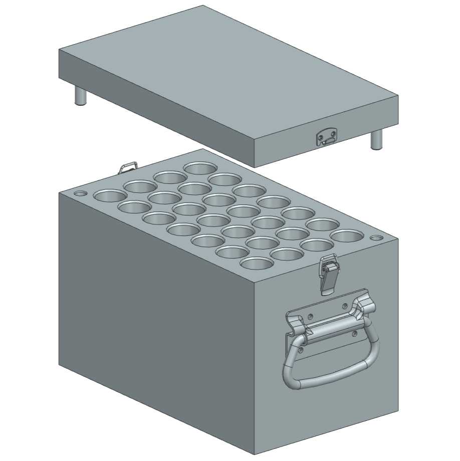
Before start
Determine the size of TANK right for you. To do this, measure the internal size of your oxidation oven and decide how many samples you can/want to oxidize at the same time. The schematics included in this protocol produce a TANK that is compatible with an HP 5890 Series II Gas Chromatograph Oven, measuring 6"(L) × 10"(W) × 7"(H) and holding up to 28, 20 mL glass ampules at a time. The internal dimensions of your oxidation oven are likely the limiting factor in the number of ampule wells you can drill. When deciding the dimensions for your TANK, remember to leave room on the sides of the oven for the handles. While the handles we recommend do collapse, the significant weight of TANK makes it beneficial to leave enough room on the sides to insert the whole unit with the handles out.
We recommend reading the protocol in its entirety before beginning production to familiarize yourself with the order of operations.
Gather materials and equipment
30m
A more detailed list of the necessary materials and equipment, including recommendations and alternatives, can be found in the "Materials" section.
Materials
- Aluminum Blocks
- 1 for Lid
- 1 for Body
- 2 Alignment post rods
- 2 Folding chest handles and corresponding screws
- 2 Latches and corresponding screws
- Cutting fluid
- Optional: Placement guides (from the provided "Blueprint and Templates" PDF), printed to scale
Equipment
- Drill bits meant for metal (at least 3/8", 7/16" and 1")
- Tap and die set
- Drill press
- Vise
- Wire brush
- 2 3/8" dowel centers
- Hydraulic press
- Center hole punch
- Belt sander
- 1" countersink drill bit
Adjust materials if necessary
2h
Before beginning drilling, adjust any materials as necessary.
For example, it is sometimes difficult to find aluminum blocks in your required dimensions. Be sure your dimensions allow room on TANK's sides for the addition of handles and clasps. Cutting the aluminum block to size before drilling holes will save time, reduce weight, and decrease the likelihood of drilling holes in the incorrect locations.
Additionally, alignment posts may need to be cut down to size.
Image depicts cutting the aluminum blocks (lid and body clamped together) to our required length with a DoALL Horizontal Band Saw (Model C-916).
To remove any sharp edges and corners, knock them down using a belt sander, file, or chamfering bit in a hand router.
Drill holes for ampules
Once your lid and body are at the correct dimensions, layout the center points for your ampule wells, being sure that no center point is closer to the long edge than 1.125" and no closer to the short edge than 1.25" (to ensure room for latch and handle screws). In addition, each center point should be at least 1.25" from one another. This can be achieved with a simple ruler and marker, a marking gauge, or (if your dimensions are equivalent to ours) a to-scale printout of the provided guide.
Create a starting point for the drill by making a divot at each center point using either a center-hole punch or a simple hammer and nail.
Note
If using the provided guide, wait to mark the center point for the alignment-post holes until later. See Step 12 for details.
15m
Ensure there is adequate clamping force applied to the block on the drill press platform. We used a 6" cross slide vise mounted to a wood board, which was in turn mounted to the platform, all with nuts and bolts.
Note
Heavy-duty clamps may be an alternative, but only if the drill press platform is of a similar size to the block and the height of the clamp does not prevent the drill bit from traveling down 5.5". Using clamps instead of the vise also means the block will need to be manually repositioned for every hole.
If you do not have a cross slide vise, but you have enough throw (i.e. there is enough vertical room to remove the drill bits with the block in place; we did not), you could change from the smaller bit to the 1" bit for each hole, so the positioning remains the same for each individual hole.
If you go this route, you will also need to change the drill speed every time.
6h
Once your block is aligned and secured, apply some cutting fluid to the divot and drill a smaller pilot hole at each divot to a depth of 5.5". We recommend a 3/8 - 1/2" bit, and a drill speed of 700-1000 rpm. This is an important step to reduce the sheer volume of material being removed by the 1" bit.
Note
For Efficient Cutting: Start slow and ensure the block does not shift when you begin drilling. It is helpful to have a second person on hand with a wire brush or a dull knife to sweep and cut away shavings and ribbons, and add more cutting fluid as needed. Be liberal with cutting fluid and raise the bit out of the hole on occasion to remove aluminum cuttings and keep the bit and block cool. You will know you have a good rpm and feed rate when the aluminum comes out in long ribbons as opposed to shavings.
Beware of the ribbons, they are sharp.
When finished with the pilot holes, clear them of cuttings with compressed air.
Safety information
This will send metal shavings flying, so take proper safety precautions: wear eye protection and do not have your head directly over the block.
Next, each ampule well must be drilled to its final size using a 1" drill bit and a drill speed of 250-400 rpm. Since you will no longer have the divots as a clear indication of center, be careful when positioning the block for the 1" hole.
Employ the same methods recommended in Step 6 for efficient cutting.
Note
We suggest that, when you think you have the block aligned properly, you slowly lower the drill bit as far as possible into the pilot hole while the drill press is off to ensure that the bit falls exactly in the center without deflection. If it does deflect, make minor adjustments so the bit is perfectly aligned. (This is why we recommend a cross slide vise as opposed to clamps; it will make these minute adjustments significantly easier.)
Image depicts drilling the final 1" wells into the aluminum block with a floor drilling press. This TANK was produced for particulate samples which require 20 mL glass ampules. Pilot holes were first drilled with a 3/8" drill bit. The block is clamped in a 6" cross slide vise, mounted to a board that is secured to the drill press platform.
12h
When all the ampule wells are finished, chamfer the edges to eliminate sharp corners. This can be done with either a large countersink drill bit in the drill press (or even a handheld drill), or a small chamfering bit in a handheld router.
Image shows chamfered edges of the ampule wells in the body. For the depicted TANK, chamfering was done with a large countersink drill bit.
Adding alignments posts
On the lid, either measure in 1/2" from each side on two opposite corners or employ a to-scale printout of the provided guide and make starting divots using a center hole punch or a simple hammer and nail.
Using the cross slide vise and the drill press, drill two holes in the lid using a 3/8" drill bit to a depth of 3/4".
Before setting the alignment post: To position the corresponding holes in the body for the alignment posts to fit into, place the dowel centers in the post holes in the lid, line the lid up with the body so the centers are touching the top of the body and the lid and body's sides are flush with each other, and gently hammer on the lid above the dowel centers to make corresponding divots in the body.
Note
This could also be accomplished by using the printout guide instead of dowel centers. However, this will likely be less accurate since even minor errors may result in misalignment. Therefore, should you go this route, employ at least a 1/2" drill bit (or possibly larger if the posts do not insert well) for the body's alignment holes to allow for inexact placement.
Using the cross slide vise and the drill press, drill two holes in the body using a drill bit between 7/16" and 1/2" (to allow wiggle room for the posts) to a depth of 1.5".
Prepare the alignment posts by sanding down the corners on a belt sander to allow for easier insertion.
Then, using a hydraulic press, set the posts into the lid.
Note
The fit should be very tight so the posts do not fall out. This is why the hydraulic press is necessary. Keep a close eye when setting the posts. Stop once the posts no longer travel any farther; any pressure beyond this point will cause the post to mushroom or deform and be unusable.
Image shows the lid with set alignment posts.
Place the lid on the body to ensure the alignment posts fit in easily. If not, redrilling the holes in the body slightly larger should alleviate the problem.
Note
You may find the lid only fits well in one orientation. If this is the case, consider adding some type of marking so you can easily identify which direction the lid fits onto the body.
Attach handles and latches
Note
If you have the appropriate equipment and training, and do not wish to use screws, you can choose to weld the latches and handles on instead.
With the lid on, place the parts of the latch on each side of TANK, ensuring there is some tension on the latch so the parts aren't too close to each other (the hook should attach to the lid and the loop to the body). Mark the screw holes with a marker. Alternatively, if you are using the recommended latches, you can use the included printout guide, but the guide should be employed as one piece with the lid sitting on the body to ensure the hook and latch are in line with one another. Then make a divot with a center hole punch or hammer and nail.
Drill holes at each marking using an appropriately sized drill bit (for the recommended No. 6 screws, use a #36 bit) to a depth of 1/2".
Then, tap the holes (for the recommended No. 6 screws, use a 6-32 tap) using some cutting fluid.
Note
These are small screws, which means the tap is quite thin for trying to cut through metal. Go slow and be careful to keep it perpendicular to the block so as to not break off the tap in the hole.
Place the handles on TANK's sides, ensuring the hinge of the handle sits at least halfway up (with the lid on) to prevent balance issues. Mark the screw holes with a marker. Alternatively, if you are using the recommended handles and dimensions, you can use the included printout guide. Then make a divot with a center hole punch or hammer and nail.
Drill holes at each marking using an appropriately sized drill bit (for the recommended No. 10 screws, use a #21 bit) to a depth of 1/2".
Then, tap the holes (for the recommended No. 10 screws, use a 10-32 tap) using some cutting fluid.
Secure the latches and handles to the sides of TANK with the appropriate screws.
Image shows the mounted collapsing handles and the draw latches, securing the lid to the body.
(The handle and latch depicted differ from the recommendations.)
Wash and dry TANK
The ampule wells and alignment-post holes will be filled with a mixture of aluminum shavings and lubricant. Prior to use, clear out the holes with compressed air to remove the shavings and scrub with water, a test tube brush, and a strong degreasing soap. Rinse well and allow to dry thoroughly.
Note
We do not recommend putting TANK in a combustion oven to remove organics (i.e. the lubricant). Since samples will be in sealed ampules, there should be no concern for contamination and it is likely that heating TANK to 500°C will result in a loss of material strength (6061 aluminum melts at 585°C). Additionally, the differing expansion rates of the aluminum block vs the steel screws/posts may undermine the integrity of the latches, handles and/or alignment posts.
Use TANK for oxidation of black carbon
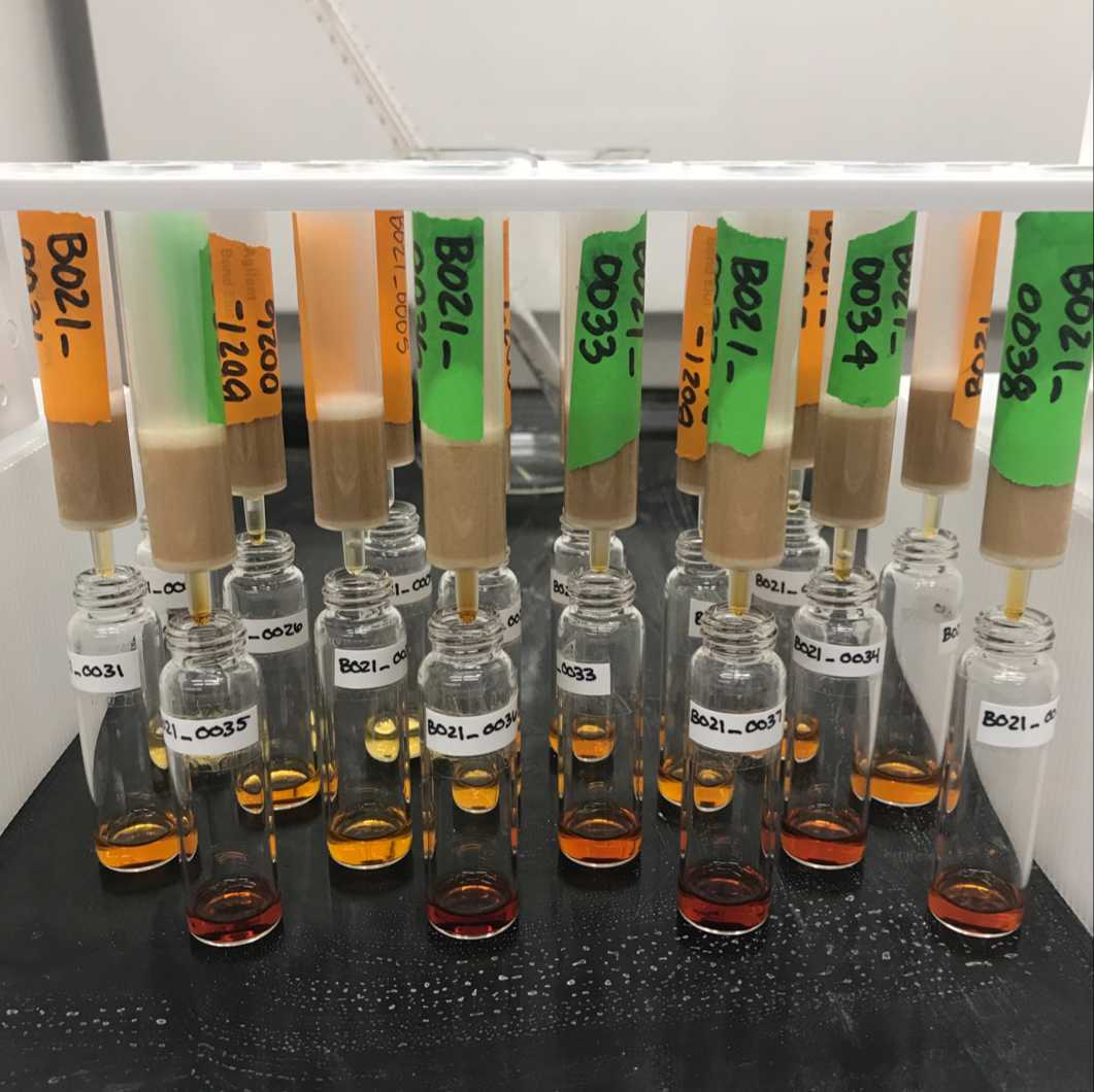
Gently place sealed ampules into the ampule wells, being careful not to drop them.
Note
Long, large tweezers may be a helpful tool for moving ampules in and out of TANK.
Step-by-step instructions for the quantification of black carbon can be found in Barton and Wagner (2022). This protocol assumes you have already put your sample and nitric acid in a glass ampule and flame-sealed it.
Place the lid on and secure it to the body with the draw latches.
Transfer TANK to your oxidation oven and run oxidation protocol.
Note
We have found that employing TANK with the BPCA protocol (Barton and Wagner, 2022) does not require any alterations in time or temperature of oxidation.
Once oxidation is complete, allow samples and TANK to return to room temperature. Then remove TANK from the oven, set aside the lid, and remove the ampules. If the ampules are still warm, or you cannot get a good grip on them, use a large pair of tweezers to grab them. Alternatively, a piece of soft tubing can be slid over the top of an ampule until snug to aid in removal.
In case of an explosion, remove all intact samples. Before cleaning, neutralize any nitric acid. To clean, tip TANK over to remove any glass, then rinse with water and dry.
Safety information
When opening TANK, assume that there has been an explosion. Wear appropriate PPE (e.g., eye protection, gloves, etc.) and perform tasks in a fume hood.
Protocol references
Barton R, Wagner S (2022) Measuring dissolved black carbon in water via aqueous, inorganic, high-performance liquid chromatography of benzenepolycarboxylic acid (BPCA) molecular markers. PLoS ONE 17(5): e0268059. https://doi.org/10.1371/journal. pone.0268059