Feb 13, 2026
Pipette Cleaning Well Assembly for Electrophysiology Systems
- Miki Lee1,
- Luke Campagnola2,
- Jessica Trinh2,
- Cliff Slaughterbeck1,
- Tim Jarsky2,
- Alex Cahoon1
- 1Allen Institute for Neural Dynamics;
- 2Allen Institute for Brain Science
- Allen Institute SIPE


Protocol Citation: Miki Lee, Luke Campagnola, Jessica Trinh, Cliff Slaughterbeck, Tim Jarsky, Alex Cahoon 2026. Pipette Cleaning Well Assembly for Electrophysiology Systems. protocols.io https://dx.doi.org/10.17504/protocols.io.3byl46w6rgo5/v1
License: This is an open access protocol distributed under the terms of the Creative Commons Attribution License, which permits unrestricted use, distribution, and reproduction in any medium, provided the original author and source are credited
Protocol status: Working
We use this protocol and it's working.
Created: September 01, 2025
Last Modified: February 13, 2026
Protocol Integer ID: 226189
Keywords: electrophysiology, patch-clamp, Tergazyme solution, reusable pipette, automated pipette cleaning, automated pipette cleaning, pipette cleaning, rapid reuse of the same pipette, automated pipette, assembly for electrophysiology system, electrophysiology experiment, pipette usability, pipette tip, clamp workflow, extending pipette usability, electrophysiology system, same pipette, clamp recording, removing contaminant, cleaning, independent waste reservoir, perfusion line, fresh solution to the well, rapid reuse, reservoir, cell patching, controlled pressure pulse, pipette, pressure pulse, failed cell patching, experiment
Funders Acknowledgements:
National Institutes of Health
Grant ID: U01NS132267
Abstract
This protocol describes the setup of hardware for automated pipette cleaning during electrophysiology experiments. In patch-clamp recordings, pipettes often become contaminated after failed cell patching or nucleus extraction, requiring replacement and slowing down experiments. Automated pipette cleaning enables rapid reuse of the same pipette, reducing downtime and increasing throughput.
The system consists of a cleaning well filled with Tergazyme solution, supplied by a height‑adjustable reservoir that controls the solution level. Perfusion line delivers fresh solution to the well, while separate vacuum lines route overflow to an independent waste reservoir. During cleaning, the pipette tip is immersed in the well and subjected to controlled pressure pulses, effectively removing contaminants. This approach enhances patch-clamp workflows by minimizing manual intervention and extending pipette usability.
Image Attribution
Image created by Miki Lee and Luke Campagnola.
Guidelines
The 3D-printed parts and tubing lengths were designed specifically for the current electrophysiology setup at the Allen Institute. The system includes he SliceScope Pro (Scientifica), Motorised Moveable Base Plate (Scientifica), PatchStar Micromanipulators (Scientifica), CV-7B Headstage (Axon Instruments), and a custom-fabricated recording chamber with a corresponding stage insert.
If integrating these components into a different system, adjust fitting parameters and trim tubing lengths as needed to ensure compatibility. Custom CAD models for all 3D-printed parts are available in Onshape: https://cad.onshape.com/documents/50b15f744a0ce64599d3af31/w/720b6081d874cfd576a499ff/e/2817c07cca84d8691984c34c
The system is operated using ACQ4, a Python-based data acquisition and analysis platform for neurophysiology. For details, see https://acq4.org/.
Materials
Custom-built parts
| Item Description | Allen Institute Part Number | 3D Printer | 3D Print Material | Quantity | |
| Z stage holder | 0347-400-01 | Bambu Lab H2D | PETG HF | 1 | |
| Pipette cleaning well | 0347-300-15 | Formlabs Form 4 | Clear V5 | 1 | |
| 50ml centrifuge tube holder | 0347-400-11 | Bambu Lab H2D | PETG HF | 1 | |
| 50ml centrifuge tube cap | 0347-400-12 | Bambu Lab H2D | PETG HF | 1 | |
| Recording chamber | 0103-020-01 | Xometry, SLA | Accura ClearVue, Matte finishing | 1 |
Custom CAD models for all 3D-printed parts are available in Onshape: https://cad.onshape.com/documents/50b15f744a0ce64599d3af31/w/720b6081d874cfd576a499ff/e/2817c07cca84d8691984c34c
For 3D printing and post-curing parameters, refer to the Properties description of each part and the “3D print setting” folder in Onshape.
- Bambu Lab H2D 0.4 nozzle (.bbscfg): Requires Bambu Lab Bambu Studio software to open the configuration file.
- Pipette cleaning well_Form 4_Clear V5 (.form): Requires Formlabs PreForm software to open the print file.
Details on Clear V5 resin material properties and the post-curing process are also available at:
Commercial off-the-shelf (COTS) parts
| Item Description | Vendor | Vendor Part Number | Quantity | Application Note | |
| One-Piece Fingertight 10-32 Coned, for 1/16" OD Natural | IDEX | F-120X | 1 | 50ml centrifuge tube cap | |
| 18-8 Stainless Steel Socket Head Screw M3 x 0.5 mm Thread, 12 mm Long | McMaster | 91292A114 | 2 | 50ml centrifuge tube holder | |
| Tergazyme Enzyme-Active Powdered Detergent | Alconox | 1304-1 | 2% w/v | Cleaning detergent | |
| Falcon 50 mL High Clarity PP Centrifuge Tube | Corning | 352070 | 1 | cleaning solution reservoir | |
| Liquid Flows Tygon Tubing Coil 1/16" x 0.02" | Darwin Microfluidics | LVF-KTU-13 | 0.9 m | perfusion, vacuum | |
| Harvard Bioscience INC G150F-3 Glass Capillary Tubing | Fisher Scientific | NC9765833 | 4 cm | pipette tip extruded to 1-2 µm diameter (4-5 MOhm tip resistance) | |
| Brass Tapered Heat-Set Inserts for Plastic M3 x 0.5 mm Thread Size, 3.8 mm Installed Length | McMaster | 94180A331 | 2 | pipette cleaning well | |
| 18-8 Stainless Steel Nylon-Tip Set Screw M3 x 0.5 mm Thread, 5 mm Long | McMaster | 93285A114 | 2 | pipette cleaning well | |
| Dow DOWSIL 730 FS Solvent Resistant Silicone Sealant White 90 mL Tube | Ellsworth Adhesives | 730 FS SOLV RES SLNT 90ML | 1 | pipette cleaning well | |
| LOCTITE EA M-21HP, 50 ml Dual cartridge | Henkel | 235017 | 1 | pipette cleaning well | |
| Tygon ND 100-80 Tubing, 2.29 mm x 1.27 mm | Darwin Microfluidics | SA-AAD04133-01 | 0.8 m | vacuum | |
| 3 WAY HI-FLO STOPCOCK | Fisher Scientific | NC9079391 | 1 | vacuum | |
| Transfer Tubing, Tygon E-Lab (E-3603), 5/32" x 3/32" | Avantor | MFLX07407-73 | 2 cm | vacuum | |
| Hose Barb Fitting, Y Union, Natural Kynar, 1/16" ID | Cole-Parmer | EW-50111-29 | 2 | vacuum | |
| Luer to Hose Barb Fitting, Straight Adapter, Natural Kynar, Male Luer, 1/16" ID | Cole-Parmer | EW-50110-09 | 1 | vacuum | |
| Luer to Hose Barb Fitting, Straight Adapter, Natural Kynar, Female Luer, 1/16" ID | Cole-Parmer | EW-50109-73 | 1 | vacuum | |
| Hose Barb Fitting, Straight Reducer, Natural Kynar, 3/32" x 1/16" | Cole-Parmer | EW-50108-48 | 2 | vacuum | |
| VWR Tygon S3 Laboratory Tubing, Formulation E-3603, 1/8'' x 1/16'' | Avantor | 89403-848 | 1 m | vacuum | |
| 1000 µL Large Orifice Tip | USA Scientific | 1011-9410 | 1 | vacuum | |
| 40mm Travel, Z-Axis Rack & Pinion Stage | Edmund Optics | 55-024 | 1 | Z stage | |
| Brass Tapered Heat-Set Inserts for Plastic M4 x 0.7 mm Thread Size, 4.7 mm Installed Length | McMaster | 94180A351 | 4 | Z stage holder | |
| 18-8 Stainless Steel Socket Head Screw 1/4"-20 Thread Size, 1/2" Long | McMaster | 92196A537 | 4 | Z stage holder | |
| 18-8 Stainless Steel Socket Head Screw M4 x 0.7 mm Thread, 10 mm Long | McMaster | 91292A116 | 4 | Z stage holder |
System Overview
System overview diagram of the pipette cleaning system.
Pipette cleaning setup on the electrophysiology system.
3D-Printed Parts
Before beginning assembly, 3D print the following components (see Materials):
- Pipette cleaning well (#0347-300-15)
- 50ml centrifuge tube cap (#0347-400-12)
- Z stage holder (#0347-400-01)
- 50ml centrifuge tube holder (#0347-400-11)
Design Guidelines: These 3D printed parts are optimized for the current rig configuration (see System Overview) and may required modification for other setups.
- Pipette cleaning well:
The cleaning well is designed to fit the custom recording chamber for ease of installation, maintenance, and replacement. It includes one perfusion channel to deliver cleaning solution and two vacuum lines to remove overflow into a moat surrounding the well.
The well height is set so that bath solution in the recording chamber does not overflow into the cleaning well. Its position allows the pipette to reach approximately 1 mm past the center of the well horizontally and ~2 mm above it vertically, providing tolerance for variations in pipette length. The well length is set to prevent interference between the objectives and the cleaning well while preserving the imaging window within the 20 mm travel range of the manipulator.
Desired accessible range of pipette tip positions indicated by the yellow box.
The mounting slot and well dimensions may be modified to accommodate other recording chamber designs and ensure the cleaning well remains reachable with different manipulators.
- 50ml centrifuge tube cap:
The cleaning solution reservoir is kept in 50ml centrifuge tube to maintain a stable solution level. The tube cap is designed so that the fingertight fitting securely holds the perfusion tube in place. Vent holes in the cap allow pressure equalization inside the reservoir, enabling initial siphon flow during priming and maintaining a stable meniscus level at the cleaning well. Minimal evaporation of the cleaning solution was observed during 8 hours of normal operation.
- Z stage holder:
The height of the Z stage holder is set so that the cleaning solution level in the reservoir tube aligns with the meniscus level at the pipette cleaning well to equalize hydrostatic pressure and stabilize the meniscus. (see Step 11.1). The holder height is optimized for the current rig configuration and may require modification for other setups; alternative mounting methods may also be used.
Assembly Instruction
Pipette Cleaning Well
CAD model of the pipette cleaning well (SolidWorks).
CAD model of the pipette cleaning well positioned on the custom recording chamber (#0103-020-01), in Onshape. The cleaning well fits within the chamber groove with clearance to allow adjustment of vertical tilt and height, accommodating variations in bath solution level.
Install two M3 heat-set inserts (#94180A331) into the holes at the back of the pipette cleaning well using a soldering iron. Slowly apply pressure at a temperature below 340°F.
Pipette cleaning well before and after inserting heat-set inserts.
Apply a thin layer of epoxy (#235017) around the periphery of each heat-set insert (front and back) to secure the inserts to the resin body of the cleaning well.
Epoxy applied around the periphery of the heat-set insert holes.
Cut vacuum and perfusion tubes to appropriate lengths (see Materials). For the vacuum line, insert 1/16″ × 0.02″ tubing (#LVF-KTU-13) into 2.29 mm × 1.27 mm tubing (#SA-AAD04133-01). Insert the tubes until they are visible entering the well and the moat.
Tubes inserted into the vacuum and perfusion channels of the cleaning well.
Apply silicone sealant (#730 FS SOLV RES SLNT 90ML) along the channels of the cleaning well and around the rear holes where the tubes pass through to fill any gaps and ensure a leak-proof seal. Let silicone sealant cure overnight.
Silicone sealant applied to create a leak-proof seal.
Insert the fingertight fitting (#F-120X) into the 50 mL centrifuge tube cap by rotating clockwise, but do not tighten all the way.
Insert the 1/16″ × 0.02″ perfusion tube (#LVF-KTU-13) into the fitting and feed it through the cap until the tube extends near the bottom of the 50 mL tube (#352070). Finish tightening the fingertight fitting to secure the perfusion tube.
Fingertight fitting and perfusion tube installed in 50 mL tube cap.
Cut the vacuum tubing to the appropriate lengths. Use a barbed reducer (#EW-50108-48) to connect the 2.29 mm × 1.27 mm tubing (#SA-AAD04133-01) to the larger 1/8″ × 1/16″ tubing (#89403-848). Join the two vacuum lines using a Y-union fitting (#EW-50111-29). See System Overview diagram.
Assembly of the vacuum tubing and fittings.
Join the merged 1/8″ × 1/16″ vacuum tube (#89403-848) from the cleaning well to the vacuum tube (#89403-848) from the recording chamber using a Y-union fitting (#EW-50111-29).
Connect the final merged vacuum line (#89403-848) to the 1/16″ ID female luer-to-hose barb fitting (#EW-50109-73) on the 3-way stopcock (#NC9079391).
Overview of the pipette cleaning well. The well has three channels:
one for delivering the cleaning solution and two on either side for suctioning
any overflow. As the cleaning solution flows through the tube and reaches the
tip of the well, it forms a convex meniscus.
Vacuum suction pipette tip
Cut the rear end of a 1000 µL large-orifice pipette tip (#1011-9410) so the cut surface fits into a male luer-to-hose barb fitting (#EW-50110-09).
1000 µL large-orifice pipette tip is cut to length.
Apply epoxy (#235017) to the cut surface of the pipette tip and insert it into a 1/16″ ID male luer-to-hose barb fitting (#EW-50110-09). Allow to cure overnight.
Cut the 5/32″ × 3/32″ vacuum tube (#MFLX07407-73) to 2 cm length and attach it to the tip of the large-orifice pipette tip (#1011-9410).
Cut the 1/8″ × 1/16″ vacuum tube (#89403-848) to length and connect one end to the 1/16″ ID male luer-to-hose barb fitting (#EW-50110-09) on the pipette tip (#1011-9410).
Connect the other end of the 1/8'' x 1/16'' vacuum tube (#89403-848) to the 1/16″ ID male luer-to-hose barb fitting (#EW-50110-09) on the 3-way stopcock (#NC9079391).
A vacuum suction pipette tip is used to initially draw
up the cleaning solution at the tip of the cleaning well and to remove excess
solution from the recording chamber.
The stopcock can be oriented to direct waste from the vacuum suction pipette tip or from overflow in the recording chamber and cleaning well into the waste bottle.
Cleaning solution reservoir holder with Z-axis stage
Install four M4 heat-set inserts (#94180A351) into the holes of the Z stage holder using a soldering iron. Slowly apply pressure at a temperature below 500°F.
Secure the Z-axis stage to the Z stage holder with four M4 screws (#91292A116).
Insert two M3 screws (#91292A114) through the holes of the 50 mL centrifuge tube holder and fasten them into the corresponding holes on the vertical mount plate of the Z stage (#55-024).
Mount the Z stage assembly onto the optics table using four 1/4″-20 screws (#92196A537).
Z stage assembly for cleaning solution reservoir.
The perfusion tube is inserted through the hole
in the 50 mL centrifuge tube cap and submerged in the cleaning solution.
Pipette Cleaning Setup and Procedure
Using a 1.5 mm hex driver, tighten the two M3 soft-tip set screws (#93285A114) to secure the cleaning well to the circumference of the recording chamber. Check to make sure the well is level and down all
the way.
Cleaning well secured to the recording chamber.
Prepare a 2% w/v Tergazyme solution (#1304-1) and pour it into the 50 mL centrifuge tube (#352070).
Submerge the perfusion tube into the solution and tighten the centrifuge tube lid. See Fig. X.
Ensure the stopcock is open along the line connected to the vacuum suction pipette tip. See Fig. X.
Using the vacuum suction pipette tip, place the tip of the tube into the cleaning well. This step initially draws up the cleaning solution to the tip of the cleaning well to create a siphon from the centrifuge tube reservoir.
Vacuum suction pipette tip placed at the cleaning well.
Once the solution is drawn into the vacuum pipette tip, remove the tip from the well. Adjust the Z-axis stage knob to raise or lower the cleaning solution reservoir until a stable convex meniscus forms at the tip of the well.
Raising the reservoir level increases the height of the cleaning solution meniscus in the well.
To maintain the meniscus level, the cleaning solution in the reservoir and the meniscus in the cleaning well should be set at the same height (Onshape).
Any overflowing cleaning solution is removed by vacuum suction through the two vacuum channels of the cleaning well.
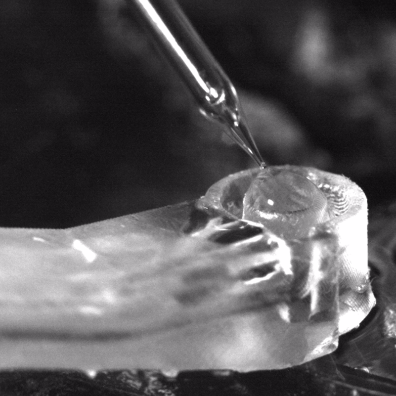
Immerse the tip of the pipette (#NC9765833) into the convex meniscus of the cleaning solution.
Example of the pipette tip submerged in a convex
meniscus of the cleaning solution.
Apply alternating positive and negative pressure cycles to dislodge and remove debris. The cleaning cycle parameters used in our setup are as follows:
- –35 kPa for 4 s
- (–35 kPa for 5 s, +50 kPa for 10 s) × 5 iterations
- +65 kPa for 5 s
Post-Cleaning Procedure
After use, the cleaning well must be cleaned. Remove the cleaning solution from the reservoir tube, then pour a small amount of ethanol into the tube.
Following the same method as step 8, draw up any remaining cleaning solution in the perfusion tube, followed by the ethanol solution, until all liquid is removed.
Pour ethanol directly at the tip of the cleaning well, allowing it to overflow and pass through the vacuum tubes. Use the vacuum pipette tip to remove any excess liquid.
Precautions
If the cleaning solution does not appear at the cleaning well, ensure that the reservoir contains enough solution, and that the perfusion tube is fully submerged. Try raising the Z-axis stage of the reservoir to see if a convex meniscus forms at the well. If it does not, manually draw up the cleaning solution using the vacuum suction pipette tip.
Ensure that the aCSF (artificial cerebrospinal fluid) solution level remains below the top of the cleaning well to prevent the cleaning solution from entering the recording chamber, as it can damage the tissue. If the aCSF level is too high, adjust the flow rate to lower it.
If the cleaning solution overflows into the aCSF, lower the Z-axis stage of the cleaning solution reservoir. Determine whether the aCSF level has risen above the cleaning well because the pressure was too high (the reservoir was too high) or if the vacuum system is weak or nonfunctional.
A weak vacuum can cause a backflow from the vacuum lines into the recording chamber and cleaning well. If this happens, bubbles may form at the cleaning well and the vacuum level should be increased accordingly.
Protocol references
Kolb, I., Stoy, W., Rousseau, E. et al. Cleaning patch-clamp pipettes for immediate reuse. Sci Rep 6, 35001 (2016). https://doi.org/10.1038/srep35001
Jehasse, K., Jouhanneau, JS., Wetz, S. et al. Immediate reuse of patch-clamp pipettes after ultrasonic cleaning. Sci Rep 14, 1660 (2024). https://doi.org/10.1038/s41598-024-51837-7
Acknowledgements
We thank Brian Lee, Ph.D. (Allen Institute, USA), Megan Koch (Allen Institute, USA), and Audrey McCutcheon (Allen Institute, USA) for troubleshooting and testing the cleaning well used in electrophysiology experiments. We also thank Martin Chase (Allen Institute, USA) for developing software enabling automated pipette cleaning.