Apr 16, 2026
Measurements of the condylar surface area of TMJ in 3D
- Anna Walczak1,
- Sylwia Łukasik1,
- Jacek Tomczyk2,
- Marta Krenz-Niedbała1
- 1Institute of Human Biology and Evolution, Faculty of Biology, Adam Mickiewicz University in Poznań, Uniwersytetu Poznańskiego 6, 61-614, Poznan, Poland;
- 2Institute of Biological Sciences, Cardinal Stefan Wyszyński University, Warsaw, Poland


Protocol Citation: Anna Walczak, Sylwia Łukasik, Jacek Tomczyk, Marta Krenz-Niedbała 2026. Measurements of the condylar surface area of TMJ in 3D. protocols.io https://dx.doi.org/10.17504/protocols.io.kqdg3n4wev25/v1
Manuscript citation:
Walczak, A., S.Łukasik, J.Tomczyk, and M.Krenz-Niedbała. 2026. “Investigating Diachronic Changes in the Temporomandibular Joint Surface With a New Approach for Three-Dimensional Surface Area Measurements.” International Journal of Osteoarchaeology1–10. https://doi.org/10.1002/oa.70112.
License: This is an open access protocol distributed under the terms of the Creative Commons Attribution License, which permits unrestricted use, distribution, and reproduction in any medium, provided the original author and source are credited
Protocol status: Working
We use this protocol and it's working
Created: December 28, 2025
Last Modified: April 16, 2026
Protocol Integer ID: 235944
Keywords: 3D measurements, surface area, temporomandibular joint, mandibular condyle, color-mapping filter , MeshLab, articular surface area, TMJ, articular surface area of the mandibular condyle, accurate quantification of temporomandibular joint articular surface, temporomandibular joint articular surface, measurements of the condylar surface area, mandibular condyle, articular surface area, condylar surface area, tmj in 3d, geometric surface area computation, surface models in meshlab, manual surface delineation, surface model, meshlab, tmj, skeletal remain, surface, 3d, skeletal remains from different population, curvature
Funders Acknowledgements:
National Science Centre Poland
Grant ID: 2024/53/N/NZ8/02043
ID-UB Initiative of Excellence—Research University
Grant ID: 102/13/SNP/0010
Disclaimer
This is an open access protocol distributed under the terms of the Creative Commons Attribution
License, which permits unrestricted use, distribution, and reproduction in any medium, provided the original author
and source are credited.
Abstract
This protocol describes a step-by-step workflow for measuring the articular surface area of the mandibular condyle using three-dimensional, surface models in MeshLab. The procedure includes curvature-based visualization, manual surface delineation, and geometric surface area computation. The expected outcome is a reproducible and accurate quantification of temporomandibular joint articular surfaces that can be consistently applied to skeletal remains from different populations and time periods.
Image Attribution
Protocol images by Anna Walczak
Guidelines
- The protocol is intended for use with high-resolution three-dimensional surface models of the mandibular condyle
- Mandibular condyles exhibiting surface damage, perforations, holes, or reconstruction artifacts within the articular region must be excluded from the analysis. Specimens with defects in the measured area must not be used, even if such defects have been digitally repaired or filled prior to analysis.
- Visualization parameters in MeshLab (e.g., lighting, shading, and color rendering settings) should be adjusted individually by the user to ensure optimal contrast between the articular surface and surrounding bone. Display calibration may influence visual interpretation but does not affect geometric measurements.
- Delineation of the articular surface using the Z-Painting tool is operator-dependent. To improve reproducibility, the same observer should perform all measurements, or inter-observer reliability should be assessed if multiple operators are involved.
- This protocol describes the procedure for performing a single surface area measurement (e.g., the left mandibular condyle). To measure both the left and right articular surfaces, all steps of the protocol must be repeated independently for each side.
- The protocol is optimized for adult mandibular condyles; its application to juvenile or pathological specimens may require additional validation.
- This protocol has been validated for surface area measurements of the mandibular condylar articular surface only. Application of this approach to other skeletal or joint surfaces has not yet been tested and would require independent validation prior to us (The authors plan to update the protocol if and when it is validated for additional anatomical surfaces).
- Accurate application of this protocol requires basic experience with MeshLab and careful delineation of the articular surface. A brief training phase is recommended prior to data collection (see Before start for details).
Materials
Required materials:
- Three-dimensional models High-resolution three-dimensional surface models of the mandibular condyle (If texture information is avaliavle prefered file format is .ply with embedded per-vertex color information. This format allows direct visualization of surface color without the use of external texture maps and is fully compatible with MeshLab).
- MeshLab software (open-source, free software)
Install from: https://www.meshlab.net/#download
Recommended equipment (for improved accuracy and workflow efficiency)
- Large, high-resolution display A monitor with a diagonal size of ≥27 inches and high pixel resolution (e.g., 2560 × 1440 or higher) is recommended to ensure precise visualization of surface boundaries and subtle morphological features. The ability to adjust brightness, contrast, and color rendering settings is particularly beneficial for optimizing the visibility of textured surfaces and enhancing contrast between adjacent anatomical regions.
- Ergonomic precision mouse A high-sensitivity, ergonomically designed mouse allowing fine cursor control is recommended to facilitate accurate manual selection of surface areas.
Before start
All observers had prior experience in handling bone models within a 3D environment. Before starting formal measurements, we recommend a short training: each observer should inspect how the curvature filters appear on the articular surface, taking into account anatomical variability, and perform several trial measurements. During our study, after the initial measurements, each extracted surface was saved, visually reviewed, and compared among the three observers to identify particularly problematic areas requiring greater attention in our case it was lateral and posterior borer of the articular surface. Based on our experience, we strongly encourage such training before formal application, although the method is overall feasible. Detailed criteria for distinguishing the articular surface are presented in Step 3 of the protocol; we recommend strictly following these criteria during all measurements.
Measurement protocol
Import the 3D model with texture into Meshlab.
Open MeshLab and import the 3D model using File → Import Mesh..., then select your. ply file. Alternatively, you can drag and drop the model directly into the MeshLab interface.
Apply the Discrete Curvatures filter.
Activate the color-mapping filter by navigating to Filters → Color Creation and Processing → Discrete Curvatures.
Identify and mark the articular surface using the Z-Painting function.
Important note:
Perform this step carefully and thoroughly, ensuring that the entire articular surface is correctly marked. At this stage, you can add or erase selections as needed.
In MeshLab, undo (Ctrl+Z) or redo (Ctrl+Y) functions are not available.
Inspect the condyle from different angles and sides to familiarize yourself with its morphology.
- Move the model: Hold the mouse wheel and drag to translate the object.
- Rotate the model: Hold the left mouse button and drag to rotate the view.
- Zoom in/out: Use the mouse wheel to zoom in or out on the condyle.
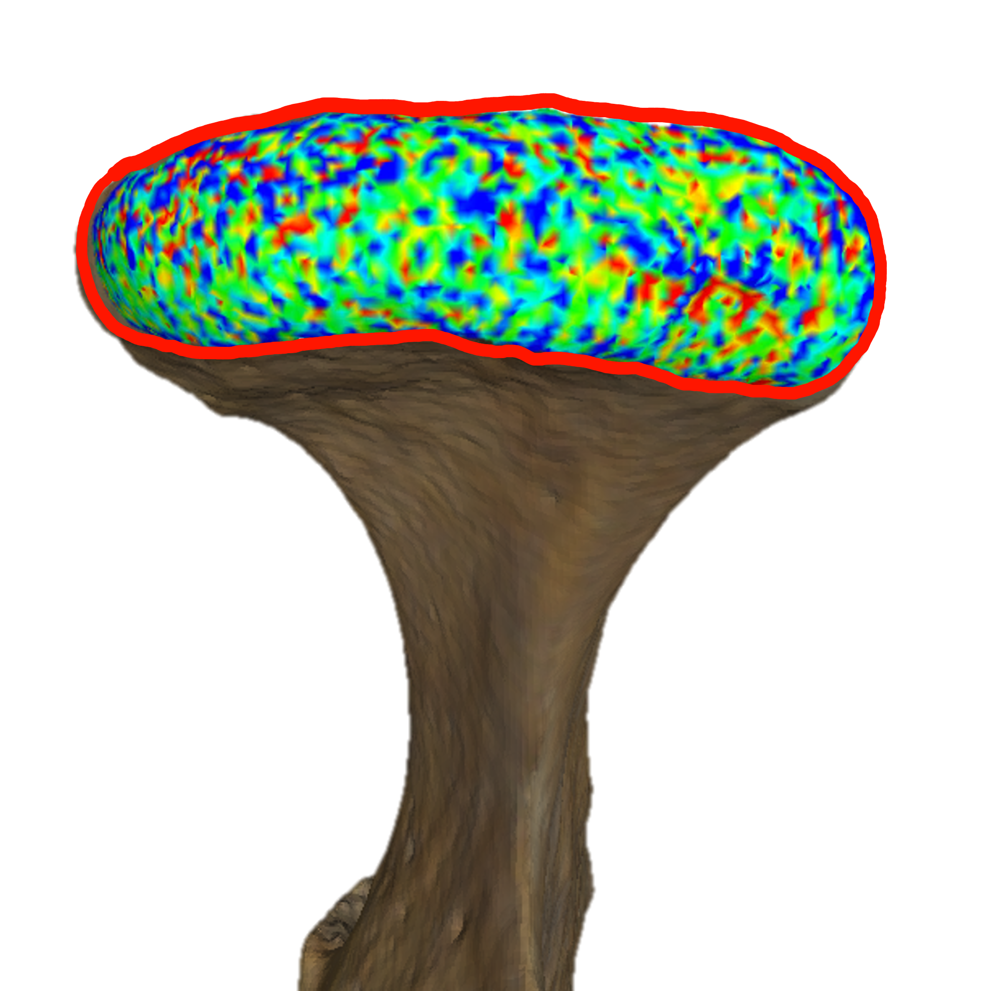
Zoom in and activate the Z-Painting function → Red Brush (Vertices Selection)
Select the articular surface you wish to measure.
Apply the criterion of following the most distinct line of blue dots along the boundary of the surface!
Using the Z-Painting function:
Select vertices: Press and hold the left mouse button and drag the cursor. Selected vertices will turn red.
Deselect vertices: Press and hold the right mouse button and drag the cursor.
Change the view: Press Esc to exit the painting mode, freely rotate or move the model, and press Esc again to return to selection mode.

Select the surface using the Select Vertices from Faces tool.
Go to Filters → Selection → Select Vertices from Faces. The selected surface will intensify in red color.
Inspect the selection carefully to ensure it fully covers the articular surface. If needed, return to Step 3 to add or erase vertices, then repeat Step 4 to confirm the final selection.
Invert the selection and delete all mandibular structures except the articular surface.
Go to Filters → Selection → Invert Selection.
Click Delete Selected Faces and Vertices.
After completing this step, only the articular surface to be measured will remain; all other mandibular structures will be removed.
Remove any remaining floating single vertices, if present.
Sometimes small areas may be selected by accident. These may be difficult to notice, but since the next step involves measuring the surface area of all remaining objects, it is important to remove any unwanted vertices.
Go to Filters → Selection → Select Small Disconnected Components. This will highlight elements that are not connected to the main articular surface. Than you can delete it by clicking on Delete Selected Faces and Vertices.
We recommend using this function as a precaution even if no floating vertices are visible.
If unwanted vertices remain, manually select them using Step 3 (Z-Painting to mark the unwanted surface), then Step 4 (Select Vertices from Faces), and remove them as in Step 5.2. Do not invert the selection in this case.
Measure the surface area of the articular region using the Compute Geometric Measures function.
Go to Filters → Quality Measure and Computations → Compute Geometric Measures.
Find the measured surface area in the lower-right panel of the MeshLab window
Copy the measured surface area value (displayed in mm²) and record it in a spreadsheet or other data collection file (e.g., Excel).
To measure the articular surface of the opposite condyle, repeat Steps 1–7 from the beginning.
Saving the measured surface for later comparison.
If you want to save the measured surface (e.g., to compare results between observers at a later stage), click File → Export Mesh As… and save the file in your preferred format. This allows you to keep a record of the exact selected vertices and surface used in the measurement.
Protocol references
1. P. Cignoni, M. Callieri, M. Corsini, M. Dellepiane, F. Ganovelli, G. Ranzuglia
MeshLab: an Open-Source Mesh Processing Tool
Sixth Eurographics Italian Chapter Conference, 2008, page 129-136
2. Karakostis FA, Harvati K.
New horizons in reconstructing past human behavior: Introducing the “Tübingen university validated entheses-based reconstruction of activity” method.
Evolutionary Anthropology: Issues, News, and Reviews 2021;30(3):185–98.
DOI: 10.1002/evan.21892
pmid:33764627