May 20, 2025
Intermediate Filament Skeleton Labeling in WEBKNOSSOS
- Alyson Petruncio1,
- CellMap Project Team1
- 1HHMI


Protocol Citation: Alyson Petruncio, CellMap Project Team 2025. Intermediate Filament Skeleton Labeling in WEBKNOSSOS. protocols.io https://dx.doi.org/10.17504/protocols.io.rm7vzxzb2gx1/v1
License: This is an open access protocol distributed under the terms of the Creative Commons Attribution License, which permits unrestricted use, distribution, and reproduction in any medium, provided the original author and source are credited
Protocol status: Working
We use this protocol and it's working
Created: February 13, 2024
Last Modified: May 20, 2025
Protocol Integer ID: 95174
Keywords: webknossos, intermediate filaments, FIB-SEM data, skeleton labeling, intermediate filament skeleton labeling in webknossos labeling, intermediate filament skeleton labeling, webknossos labeling, official knossos documentation page, source platform webknosso, intermediate filament, sem data, sem, fib,
Abstract
Labeling of intermediate filaments in 4nm FIB-SEM data using the open-source platform WEBKNOSSOS. All navigation, segmentation, and data import documentation can be found on the official KNOSSOS documentation page: https://docs.webknossos.org/webknossos/
Import FIB-SEM Data into WEBKNOSSOS
WEBKNOSSOS does not require software-specific file conversion and supports the following bio-imaging dataset file formats for import and streaming:
Open WEBKNOSSOS (https://webknossos.org/). Create account, and select 'Datasets' tab to add, remove, and view all imported datasets. To add a new dataset, select the '+ Add Dataset' button.
Specify Dataset Name and Target Folder if uploading from a local hard disk, or specify Dataset URL if streaming a dataset from the cloud or remote servers.
Once dataset is imported, under the Dataset dashboard, select 'View' or '+ New Annotation' to view the dataset.
Dataset and options within Dataset tab of Dashboard
Assess FIB-SEM Data for Optimal Labeling Strategy and Identify Filaments
In order to optimize skeleton continuity and accurate identification of intermediate filaments, navigate through each dataset window to find the orthogonal plane with the closest axis view of filaments.
- Intermediate filaments are ~10 nm in diameter and continue for at least 600 nm. Continuity and flexibility varies widely, but filaments will often maintain a consistent FIB-SEM staining contrast and move in bundles through centers of cells, sparsing out towards cell membranes. Intermediate filaments can change direction abruptly, but don't often bend below a 90° angle.
- Ribosomes are ~200% the diameter of intermediate filaments and not continuous. Ribosome and intermediate filament FIB-SEM staining contrast is often similar. Staining often overlaps, indicated by a sudden change in filament diameter when scrolling through the dataset.
Orthogonal planes of FIB-SEM dataset containing intermediate filaments; the axis view of filaments is found in the XZ plane (circled in red), while other orthogonal views show lengthened view of filaments (circled in blue).
Once the axis-facing plane is identified, expand the window using the window icon in the top right corner of each orthogonal view. Using the mouse wheel, or d/f (+ Shift for faster scrolling), navigate through the selected plane to identify patterns in filament 'movement' and continuity. Visually track an identified filament to the edge of the dataset. Initiating skeleton trees on a dataset edge will increase segmentation efficiency.
Create a Skeleton Tree
Skeleton segmentations are composed of trees. Each filament is considered a separate tree and has a unique tree ID. Intermediate filament trees do not branch, so new tree nodes must be added to a selected end node.
Create a tree by first selecting 'c', which creates a new tree ID and color under the 'Skeleton' tab of the right sidebar. To place the first node, hover the mouse cursor over the center of an intermediate filament axis point and left click while in Skeleton Mode (see below).
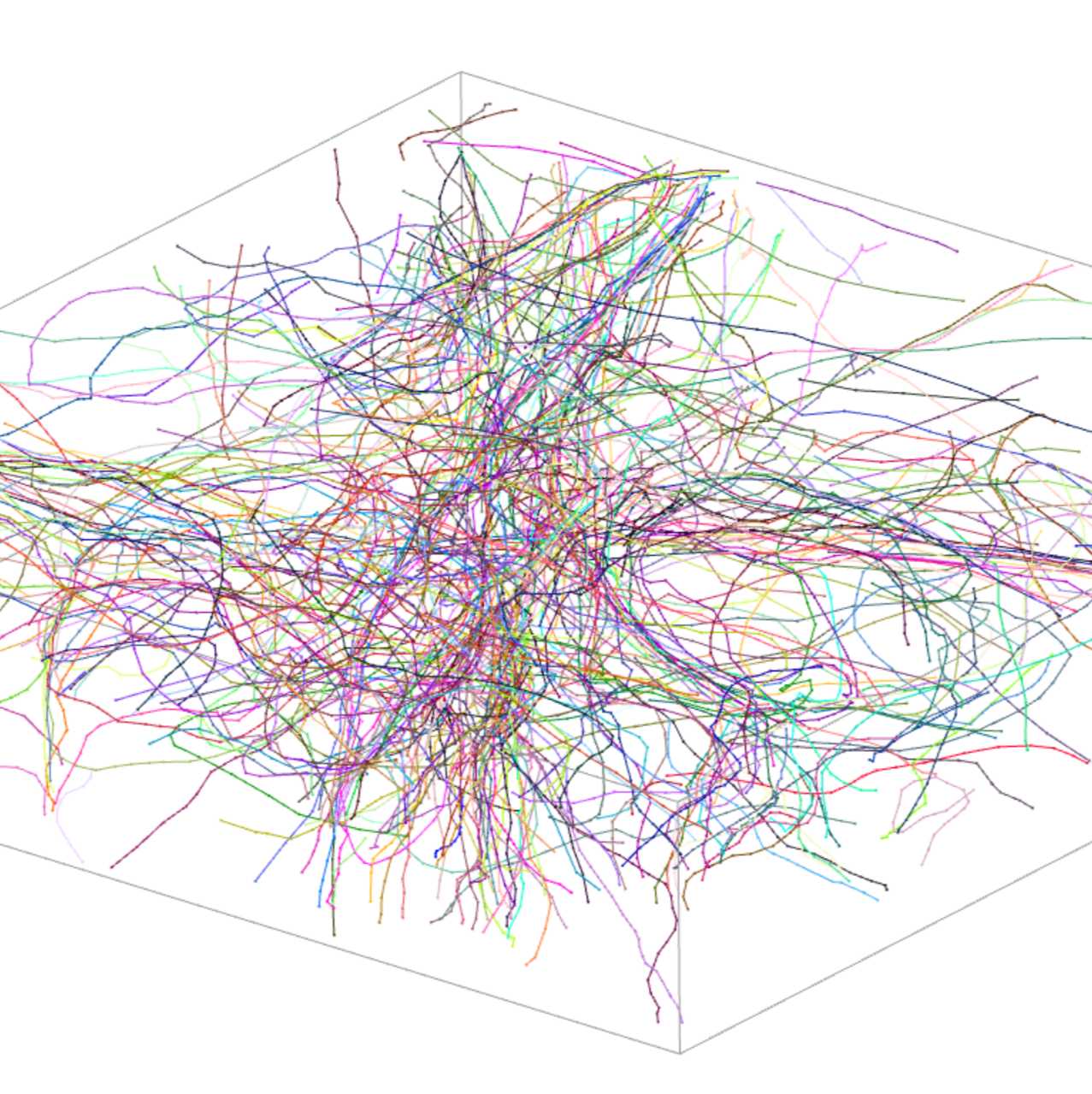
Node and dataset settings can be modified in the left sidebar, and annotation info and settings can be modified in the right sidebar. The 3D Viewer provides real-time visualization of skeletons, color coded based on tree ID.
'Move Mode' (far left icon) and 'Skeleton Mode' (icon circled in blue) are used for click+drag movement across the dataset planes or node selection and adding or moving nodes, respectively.
After placing a node, scroll through the dataset until the tracked filament begins to subtly change trajectory. Hover over the center of the filament axis and left click.
As nodes are placed, refer back to other plane views to verify if node placement is accurate to the filament, does not 'jump' filaments, and continues or terminates. Nodes can be placed in any plane view from a selected end point during node placement.
At any point, a new tree ID and color can be created by selecting 'c'. Select a different tree for node editing in the Skeleton tab of the right side bar. Use the Move Mode to select an end node in order to continue with tree segmentation.
Toggle tree visibility (active or inactive) or select individual tree IDs from the Skeleton tab of the right side bar to visualize individual or multiple trees in the 3D viewer and plane views.
Merge, Split, and Remove Skeleton Trees and Nodes
In the event of a skeleton segmentation error, removal of individual nodes from trees can aid in efficient tree correction, especially when a single tree ID includes two or more filaments. Similarly, merging capabilities allow for piecewise skeleton segmentation if needed.
If an incorrect node was placed, select the incorrect node with a left click, then select Del. The new active node will be the next consecutive node in the tree. If a node is deleted from the center of a tree, the tree will split into two unique IDs.
When two separate tree IDs need to be merged into a single filament, select the end node (in 'Move Mode') of one tree that is closest to the other tree end node to be merged. Right click on the other filament end node, and select 'Create Edge & Merge with this Tree' from the dropdown menu. The resulting single tree ID will take the ID of the last selected node.
Tree ID 1 (orange) will be merged with tree ID 2 (brown), and become tree ID 1 (orange)
Skeleton Export
Download all segmented skeleton trees in NML format by selecting 'Menu' → 'Download'.
Alternatively, download only specific tree IDs by selecting and deselecting tree IDs under the 'Skeleton' tab of the right sidebar. From the 'More' dropdown menu, select 'Download Visible Trees' to export an NML file.
Protocol references