May 09, 2025
Fabrication and calibration of multi-fiber arrays to monitor dopamine release in the mouse striatum
Forked from Multifiber Array Fabrication
- Mai-Anh Vu1,2,
- Safa Bouabid1,2,
- Mark Howe1,2
- 1Department of Psychological and Brain Sciences, Boston University, Boston, MA, United States;
- 2Aligning Science Across Parkinson's (ASAP) Collaborative Research Network, Chevy Chase, MD, 20815, USA


Protocol Citation: Mai-Anh Vu, Safa Bouabid, Mark Howe 2025. Fabrication and calibration of multi-fiber arrays to monitor dopamine release in the mouse striatum. protocols.io https://dx.doi.org/10.17504/protocols.io.3byl4z272vo5/v1
License: This is an open access protocol distributed under the terms of the Creative Commons Attribution License, which permits unrestricted use, distribution, and reproduction in any medium, provided the original author and source are credited
Protocol status: Working
We use this protocol and it's working
Created: March 25, 2025
Last Modified: May 09, 2025
Protocol Integer ID: 125041
Keywords: multi-fiber, photometry, mouse, dopamine release in the mouse striatum, dopamine release, dopamine, fluorescent sensor, array fabrication, mouse striatum, spatial resolution, calibration, behaving mice, mouse, striatum
Funders Acknowledgements:
Aligning Science Across Parkinson’s (ASAP)
Grant ID: ASAP-020370
Abstract
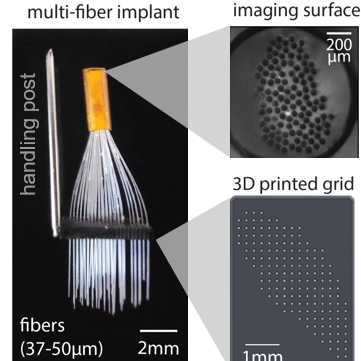
We have developed a multi-fiber photometry approach to monitor dopamine release with sub-millimeter spatial resolution and sub-second temporal resolution at over 50 locations simultaneously throughout the striatum in awake, behaving mice expressing a fluorescent sensor. This protocol includes the array fabrication and pre-implant mapping steps.
Please contact us ([email protected]) if you are interested in using this technique.
Materials
Equipment:
- 37µm (34µm core, 3µm cladding) or
- 50µm (46µm core, 4µm cladding)
- Custom 3D printed biocompatible plastic grid (Boston Micro Fabrication)
- 3mm x 5mm
- our holes were spaced radially by 220 microns
- Polyamide tubing (Cole-Parmer or MicroLumen)
- 0.8-1.3mm diameter
- 5- or 6-micron
- 3-micron
- Razor blades
- Dissection microscope for fabrication
Helpful but not necessary:
- Smooth thin paper for the calibration step; we have found that a tiny piece (5mm x 10mm) of Tyvek USPS mailing envelope colored black with a marker works well
Fabrication of Multi-Fiber Arrays
Cut fibers into several ~3 cm pieces using the ThorLabs fiber scribe.
Secure the grid to the Helping Hands using one of the clamps and paper tape.
Under the microscope, load fibers into the desired holes in the first row of the grid.
Note
The design of these implants is completely flexible.
Our designs are meant to target the striatum with maximal coverage with no overlap in the collection fields of individual fibers.
Rotate the grid such that the fibers are now parallel to the lab bench.
Under the microscope, push/pull the fibers to the desired depths on the implanted side beneath the grid.
Rotate the grid such that the top is visible, and apply UV glue to the loaded holes.
Under the microscope, push/pull the fibers to the desired depths on the implanted side beneath the grid.
Verify that the lengths are correct, and then cure.
Repeat steps 2 to 7 for the remainder of the rows.
Note
We do this row by row, but column-by-column or hole-by-hole is possible.
Once all fibers are loaded and secured, gather the fiber distal ends into a ~1cm section of polyamide tube.
Fill the tube with instant glue and let dry.
Cut with a fresh razorblade – this cross-section is the imaging surface.
Polish first with the 6 micron polishing paper, and then the 3 micron to create a smooth, uniform fiber bundle surface for imaging.
Mount a large diameter post (this can be a blunted, sanded section of a needle) on one side of the grid to facilitate holding during implantation.
Calibration of Multi-Fiber Arrays
Mapping the fiber grid location to imaging surface
The goal is to use the LED penlight to illuminate the implanted ends and note which fibers in the imaging surface are lit. Do this by sequentially uncovering one row at a time, and then one column at a time, such that each fiber in the imaging surface has a row and column coordinate in the grid.
Below is an example on how to calibrate the multi-fiber arrays:
Flip the multi-fiber array upside down, so the implanted ends are upwards.
Mount the USB digital microscope camera underneath to have a clear view of the imaging surface.
Under the dissection microscope, use a piece of paper (material #14 above) bent to 90 degrees, slot it between the first and second rows such that rows 2 onwards are covered.
Shine the LED light on the exposed fibers and note (taking a picture is useful) the illuminated ends in the imaging surface.
Slot the piece of paper between rows 2 and 3, such that rows 1 and 2 are exposed, and rows 3 onward are covered, and repeat step 15.4.
Repeat for the remainder of the rows.
Repeat for the columns.