Oct 17, 2025
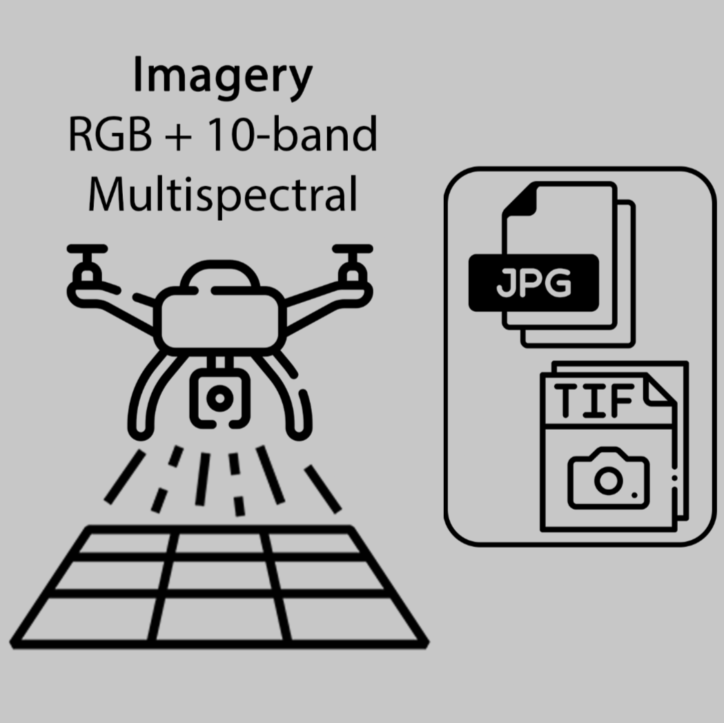
DroneScape: Collection of RGB and 10-Band Multispectral Imagery for Ecosystem Plot Monitoring
- Juan Carlos Montes-Herrera1,2,3,
- Alice Robbins2,
- Carla Franson1,3,
- Troy Bektas1,3,
- Ben Sparrow1,3,
- Arko Lucieer2
- 1Terrestrial Ecosystem Research Network (TERN);
- 2School of Geography, Planning and Spatial Sciences, University of Tasmania;
- 3School of Biological Sciences, The University of Adelaide
- MontesHerrera


Protocol Citation: Juan Carlos Montes-Herrera, Alice Robbins, Carla Franson, Troy Bektas, Ben Sparrow, Arko Lucieer 2025. DroneScape: Collection of RGB and 10-Band Multispectral Imagery for Ecosystem Plot Monitoring. protocols.io https://dx.doi.org/10.17504/protocols.io.rm7vzk2e5vx1/v1
License: This is an open access protocol distributed under the terms of the Creative Commons Attribution License, which permits unrestricted use, distribution, and reproduction in any medium, provided the original author and source are credited
Protocol status: Working
We use this protocol and it's working.
Created: January 26, 2025
Last Modified: October 17, 2025
Protocol Integer ID: 119074
Keywords: uav, drone, monitoring, mapping, landscape, ecology, RGB, multispectral, orthomosaic, band multispectral imagery for ecosystem plot monitoring, dji matrice 350 drone, multispectral imagery, dronescape, band multispectral imagery, hectare ecosystem plot, multispectral orthomosaic, ecosystem plot monitoring, uav protocol, sensors dji zenmuse p1, creation of uav protocol, georeferencing, dji rtk base station, dji matrice, gimbal mount, simultaneous rgb, collection of rgb, subsequent alignment of imagery, imagery, rgb
Disclaimer
In the context of this protocol, we use the term 'drone' to refer to a remotely piloted aircraft system (RPAS) also referred to as uncrewed/unoccupied aerial vehicle (UAV) or uncrewed/unoccupied aircraft system (UAS). This protocol assumes that the operator is already familiar with the assembly of the DJI Matrice 350 drone as outlined in the DJI Official User Manual. It is not a substitute for the comprehensive assembly instructions in the manual.
Approvals and procedures for land-access, permits, drone operations, and compliance as per national regulations (e.g., Australian Government Civil Aviation Safety Authority (CASA) regulations) are outside the scope of this document. The protocol is best used with two staff: a pilot and a spotter.
Abstract
This protocol describes the procedures for deploying a DJI Matrice 350 drone equipped with a dual-gimbal mount to collect simultaneous RGB and 10-band multispectral imagery of 1-hectare ecosystem plots. The sensors DJI Zenmuse P1 and MicaSense RedEdge-P Dual are used.
The protocol includes flight planning and data collection procedures to cover a 100 x 100 m (1 ha) area, with a varying margin of 0 to 100 m (up to 300 x 300 m). Georeferencing is achieved using a DJI RTK base station. A key feature of this workflow is the subsequent alignment of imagery from both cameras into a unified model and produce RGB and multispectral orthomosaics (see Data Processing Protocol). The steps outlined here support the creation of UAV protocols and analysis-ready data products for TERN's programs.
Image Attribution
Flaticon.com & Juan C. Montes-Herrera
Guidelines
- Approvals and procedures for drone operations and compliance as per flying regulations are outside the scope of this protocol.
- Coordinate with local authorities and landowners to ensure all permissions and road access are obtained before conducting flights.
- Ensure all drone operations comply with official aviation safety regulations. For Australia, check Civil Aviation Safety Authority (CASA) regulations and the organisation’s Remotely piloted aircraft operator's certificate (ReOC) processes.
- Both the pilot and spotter must be certified to operate the DJI Matrice 300/350 RTK drones and trained in emergency landing protocols.
- Conduct pre-field Job Safety Assessments (JSAs) for each flight mission and submit them to the Chief Remote Pilot for approval.
Materials
Google Earth Pro for mission preparation.
Dual Gimbal DJI M300 or M350 case containing:
- DJI Matrice drone with dual gimbal and downwelling light sensor (DLS) connected.
- Remote controller and charger
- Tablet or phone for MicaSense user interface and charger
- MicaSense Calibrated Reflectance Panel (CRP)
- Spare propellers
DJI Zenmuse P1 sensor case containing the sensor, SD card, spare SD cards, and quality cleaning cloth.
MicaSense RedEdge-P/Dual case containing the sensor, CF express cards, spare CF cards, and CF card reader (If using RedEdge-MX model, use SD storage cards).
Matrice battery charging station containing:
- M300 or M350 batteries (x8)
- USB-C cables (x2)
- D-RTK2 batteries (x4)
DJI D-RTK2 Mobile Station antenna, tripod and extension rod.
Tools:
- DGPS unit
- Sturdy rubber mat to launch/land drone
- Star pickets, filing tool, battery-powered engraver, and flagging tape to mark the location of D-RTK2 base if site revisit is likely
- Laptop for data backup, formatting cards, etc.
- SD and microSD card reader
- Case to secure and store memory cards
- Tool kit with spare parts: gimbal grommets, spare gimbal covers and lens caps, spare screws of types used; screwdrivers, and cable ties.
- First aid kit
- Radios and air band radio
- Generator (if required to charge batteries in the field).
Memory Card Specifications and Storage Capacity
Below are the specifications and requirements for memory cards used with each sensor, including recommendations for sufficient storage capacity per field day, which typically involves capturing data from 3 to 5 plots (16 ha each).
Zenmuse P1
- Recommended Memory Card: SD card UHS-I or higher; maximum capacity of 512 GB.
- Storage Needs: Approximately 30 GB per plot with a 50 m margin; around 150 GB for a typical day.
MicaSense RedEdge-P/Dual
- Recommended Memory Card: Delkin Devices Power CFexpress card 128 GB (FAT32 formatted).
- Storage Needs: Estimated 60 GB per plot with a 50 m margin; about 300 GB for a typical day.
Older Multispectral Model (MicaSense-MX Dual)
- Recommended Memory Card: SDHC Class 10 with minimum write-speed of 40 MB/s and read-speed of 90 MB/s.
- Storage Needs: 50 GB per plot with a 50 m margin; 250 GB for a typical day.
Backup Storage
- Two Portable 4 TB SSDs for efficient data backup.
- Recommended Product: Samsung T7 Shield 4TB USB-C Portable SSD.
Troubleshooting
Problem
Unable to lock sensor to Gimbal
Solution
Press release button and manually rotate the gimbal to the unlocked position.
Safety warnings
- Store batteries in a dry, ventilated area at room temperature and avoid leaving them unattended in vehicles.
- Ensure battery cases are labeled for transport (e.g., Class 9 - Miscelleanous dangerous goods)
- Do not operate the drone in rain, precipitation, or wind speeds exceeding 18 m/s.
- Ensure flight operations are paused if obstacles or hazards are detected in the surroundings.
- Comply with official aviation safety regulations.
- Do not leave the Calibrated Reflectance Panel (CRP) open exposed to dust, only open and use for calibration image collection.
Ethics statement
- Avoid disturbing wildlife.
- If needed, use non-invasive reference points for marking base stations in protected or sensitive areas, such as close to roads and national parks.
- Adhere to ethical data collection practices that prioritise safety and minimise environmental impacts.
Before start
Before departure
- Inspect all drone equipment for visible damage or wear, including airframe, propellers, sensors, landing gear, and batteries.
- Verify that the latest firmware is installed on all devices, including the drone, sensors, remote controller, and D-RTK2 base station. Note: Some labs may have specific protocols for firmware updates or may prefer that a designated person carries out this task. Always check with lab-specific procedures before proceeding.
- Charge all batteries to full capacity one day before the mission, and store in LiPO safe storage. Do not use damaged or swollen batteries.
- Verify that memory cards are properly formatted and sufficient storage is available for fieldwork.
- If unsure of internet access in the field, pre-cache study area imagery in the DJI Pilot app before departing for fieldwork.
Flight Operational Safety
- Manually check and calibrate the compass at each site after significant travel distance.
- Ensure sensor is secured and working correctly.
- Ensure mapping mission is safe and spatially accurate.
- Use manual takeoff and landing to maintain control, particularly in areas with uneven terrain or obstructions.
- Maintain constant communication between the pilot and spotter, especially near roads or other potential hazards.
- Always monitor the drone speed, altitude, and battery levels during the mission to ensure safe operations.
- Monitor correct sensor exposure, position and angle during mission flight time, use the multiple view options (e.g., P1 camera view, FPV).
Field cheat sheet - Optical imagery mapping mission settings
dronescape: RGB+10-band multispectral field cheat sheet
| Parameter | Value | Note | |
| General Settings | |||
| Area Route | PlotID-YYYYMMDD-P1 | E.g. (NTAFIN0011-20250120-P1) | |
| Aircraft | M300/M350 RTK | ||
| Camera | P1 | ||
| Lens | 35 mm | ||
| Focus Mode | First Waypoint Autofocus | ||
| Dewarping | Disabled | ||
| Ortho Collection | Enabled | ||
| Ortho GSD | Default | ||
| Altitude Mode | Relative to Takeoff Point (ALT) | ||
| Route Altitude | 80 m | ||
| Elev Optimization | Enabled | ||
| Safe Takeoff Alt | 20 m | Pilot to assess. | |
| Speed | 8 m/s | ||
| Course Angle | 0 | ||
| Upon Completion | Return to Home | ||
| Advanced Settings | |||
| Target to Surface (TS) | 0 | Pilot to assess (see Table in Mission Planning section) | |
| Side Overlap | 80% | ||
| Frontal Overlap | 80% | ||
| Margin | 100 m | Pilot to assess if needs to be reduced; roads, land property, safety, etc. | |
| Photo Mode | Timed Interval Shot | ||
| Camera Angle | Disabled | ||
| Route Start Point | - | Set to the farthest point from takeoff site. | |
| Takeoff speed | Default | ||
| P1 Sensor Settings | |||
| Capture Mode | M - Manual Mode | ||
| ISO | Auto | ||
| Shutter Speed | 1/1000 | ||
| Aperture | 5.6 | ||
| Image Ratio | 3:2 | ||
| Image Format | JPG | ||
| White Balance | Sunny or Cloudy | See Sky Code Table in P1 settings section. | |
| Style | None |
Optical imagery flight mission planning settings in DJI Pilot 2 app for quick use in the field.
Mission Planning - Google Earth Polygon (or preferred GIS)
Note: If a historical polygon in a compatible format (e.g., .KMZ, .KML or .SHP) is available, can skip to next section.
Open Google Earth Pro to create KML files for each 1 ha plot to be surveyed during field trip.
Load KMZ file of plot corners or polygon area to be mapped. If not available, navigate to the area of interest to create polygon.
- For existing plots refer to previous documentation to download exact coordinates for each plot corner.
Within Google Earth click 'Add Polygon'
Notice cursor icon change (white cross box on map screen), click once on each plot corner (red circles).
Name polygon, best to use standardised Plot ID.
Click OK
- Right click Polygon layer on sidebar, then 'Save Place As...'
- Save as KMZ file.
- Store in the DJI controller memory via USB cable or microSD card.
Advanced: Assessing topographic complexity of study area.
For monitoring plots established with steep slopes or elevation changes, enabling Terrain Follow in the flight mission settings during data collection is recommended to ensure consistent image overlap.
Selecting the appropriate Terrain Follow parameter and Digital Elevation Model (DEM) is dependent on the drone platform and the study area.
Options for Terrain Follow:
1. Import Local File (recommended): review the spatial data available for the study area using (e.g., for Australia; Elvis – Elevation and Depth – Foundation Spatial Data). Availability of elevation data can be limited in remote areas.
- If there is a suitable elevation model available for the study area, select the data required and complete the relevant fields to order data from online provider.
- It is critical to select WGS84 Lat/Longs (EPSG:4326) to ensure the local DEM is compatible with DJI Pilot 2.
- The local DEM can be imported directly onto the drone controller or onto a microSD card and selected during mission planning
2. Download directly from DJI Pilot during mission planning (below): if this option is selected in DJI Pilot 2 during mission planning (Altitude Mode -> AGL -> DSM Files -> Download from Internet) the ASTER Global Digital Elevation Map (GDEM) will be used for Terrain Follow.
- The resolution of this DEM is approximately 30 metres and caution should be taken with using this elevation model in complex terrain or to map complex/tall vegetation.
Mission Planning - DJI Pilot App
Prepare 2D mapping mission settings with DJI Controller
- Select Flight Route
- Within the Library, press '+' icon on top right -> Import Route (KMZ/KML)
- Load mission by navigating the memory to the KMZ file stored in previous step.
- Select flight mission and click 'Confirm'.
- Allow access to SD card.
- Select Area Route
- On the top left, toggle the mission menu, and click the 'Edit' icon (Pencil)
Mapping Mission - General Settings
A panel to edit the mapping mission settings should appear on the right. Follow the table below to adjust the general mapping settings.
| A | B | C | |
| Parameter | Value | Note | |
| Area Route | YYYYMMDD-PlotID-P1 | E.g. (20250120-SAAEYB0006-P1) | |
| Aircraft | M300/M350 RTK | ||
| Camera | P1 | ||
| Lens | 35 mm | ||
| Focus Mode | First Waypoint Autofocus | ||
| Dewarping | Disabled | ||
| Ortho Collection | Enabled | ||
| Ortho GSD | Default | ||
| Altitude Mode | Relative to Takeoff Point (ALT) | ||
| Route Altitude | 80 m | ||
| Elev Optimization | Enabled | ||
| Safe Takeoff Alt | 20 m | Pilot to assess. | |
| Speed | 8 m/s | ||
| Course Angle | 0 | ||
| Upon Completion | Return to Home |
Mapping Mission - Advanced Settings
Target Surface to Takeoff Point
- Target Surface to Takeoff Point parameter depends on canopy height (CH) and terrain complexity.
- Similarly the difference in terrain between plot and the drone takeoff area must be considered when setting a suitable target surface.
- This is essential to ensure that the overlap calculations are applied appropriately. When the terrain to map and the takeoff point differ in elevation, set this to the distance from the takeoff point to the target surface.
- For tall canopies >30 m, flight altitude might be automatically changed by the DJI Pilot App, assess for flight regulations and safety.
| A | B | C | |
| Parameter | Value | Note | |
| Side Overlap | 80% | ||
| Frontal Overlap | 80% | ||
| Margin | 100 m | Pilot to assess if needs to be reduced; roads, land property, safety, etc. | |
| Photo Mode | Timed Interval Shot | ||
| Camera Angle | Disabled | ||
| Route Start Point | - | Set to the farthest point from takeoff. | |
| Takeoff speed | Default | Manual takeoff recommended. |
- Important: For safety, the final flight margin should be determined in the field. However, previous mission planning helps to anticipate any constraints, such as roads or private land, that may cause a reduced margin.
Save Mission 💾
Double-check flight estimated duration, altitude, route, and any modified settings.
In the Field: DGPS and D-RTK2 Base Station Setup
The dual frequency RTK GNSS in the M300/M350 enables direct georeferencing of images using DJI D-RTK2 base station.
Navigate with the DGPS pole, tablet for DGPS app, and the DJI D-RTK2 base station (ensure full battery), towards a plot corner easily accessible from the drone launch area.
Note that the preference is to use the plot corner closest to drone launch area. The base station must be in an open area to prevent GNSS signals from being blocked. In woodlands or dense canopies look for flat open ground within 15m of the corner, if not viable locate a suitable area close to the plot corner (within 200m).
D-RTK2 base station established on top of a permanent marker stake in proximity to a plot corner. Below the hammer used for grounding stake, and DGPS blue pole used for coordinate retrieval.
Permanent Marker Establishment
As necessary, the plot corners can also be used as a permanent marker for future surveys, without need of a ground stake.
Stake ground exactly where DGPS point is intended to be collected.
- If using short stake (45cm) – hammer flush with surface and cap.
- If using taller stake (150cm) – hammer 1/3rd into substrate and cap.
In some cases, harder or rocky substrates may prove difficult to drive in a stake resulting in partially exposed stakes. In this situation the height of the stake after being capped must be measured and subtracted from the 1.8m pole so that the height of the pole remains 1.8m from the ground when placed on top of the capped stake.
Capped ground stake used as central position for D-RTK2.
- Check that the battery in D-RTK2 antenna is fully charged.
- Power up the antenna by clicking Power button twice and hold.
- Ensure the third LED (left to right) has a blinking pattern of 5 times. This indicate DRTK is operating in Mode 5. If necessary, long press the Mode button for 2 seconds to change Mode.
- Take a photo of the entire base station and include this in the metadata folder.
Adjust D-RTK2 base station coordinates.
1. Open the Mission screen on the DJII Pilot App
2. Press '...' on the right side of the main menu
3. Go to RTK and toggle RTK Positioning ON
4. Set RTK Service Type to D-RTK2 Mobile Station
5. Open Advanced Settings (password: 123456)
6. Select ADJUST COORDINATES and enter the known DGPS coordinates for the plot corner.
Adjusted coordinates:
- If DGPS provides Latitude, Longitude, and Altitude (from a DGPS list or direct reading): Enter Lat/Lon (8 decimal places) and add 1.8 m to the DGPS Altitude.
- If only Latitude and Longitude are available: Enter them and leave altitude as is.
Press Save and restart the aircraft.
If a persistent RTK base station error appears, restart the base station, verify the coordinates, and restart the aircraft.
Check RTK settings:
- D-RTK2 Mobile Station Status is connected.
- Base station coordinates have been updated.
- Aircraft Orientation and Positioning FIX status.
- RTK icon on top displaying number of satellites.
Prepare Aircraft and Sensors
This protocol assumes that the operator is already familiar with the assembly of the DJI Matrice 350 RTK aircraft as outlined in the DJI Official User Manual. It is not a substitute for the comprehensive assembly instructions in the manual.
- Check Components: Confirm all parts, including aircraft, propellers, batteries, controller, dual-gimbal, and downwelling light sensor (DLS) are present, and in good conditions.
- Install Batteries: Insert fully charged batteries until they click into place, ensure to use labeled pairs.
- Turn ON Aircraft.
Compass calibration must be performed at all sites following significant travel. It is recommended to do this step before the sensors are installed to avoid damaging the sensors or gimbal dampeners. To calibrate the compass, follow the steps below:
- Click on the ‘…’ on the right-hand side on the main screen
- Click on the drone image in the following screen to access ‘Flight Controller Settings’. Scroll down and select ‘Sensor Status’.
- Click on the Compass tab. Click on ‘Calibrate Compass’ and follow on-screen instructions to calibrate the compass. The process involves rotating the aircraft around the vertical and horizontal axes.
Install DJI Zenmuse P1 (RGB camera)
- Check that P1 camera has an SD card.
- Press the Gimbal 1 detachment button to remove the cover.
- Align the white dot on the P1 with the red dot on Gimbal 1 and connect. Rotate the gimbal lock to the locked position (red dots aligned).
- If unable to rotate gimbal lock, it is possibly stuck. While pressing the gimbal button, manually rotate the lock to its unlocked position (white dot).
Install MicaSense RedEdge-P Dual (or RedEdge-MX Dual)
- Check that both MicaSense sensors have CF Express cards.
- Press Gimbal 2 detachment button to remove the cover and mount MicaSense cameras.
- Connect Downwelling Light Sensor (DLS) to the camera DLS port.
(a) Install P1 camera on Gimbal 1 and the MicaSense sensor on Gimbal 2 (RedEdge-P dual sensor shown here). Connect the power cable and DLS on MicaSense sensor. (b) If the sensor does not fit in the gimbal socket, check the alignment of the socket, and rotate the pins manually while pressing the release button.
Remove lens caps from all sensors.
Turn ON the aircraft.
P1 Camera Settings
Preparing to fly
- Load the previously saved Mission File from the Flight Route Library.
- Once mission has been loaded, click on bottom left square (or press L3 in the controller) to enter P1 camera settings.
Within the P1 camera, click top right icon to select capture mode:
- Ensure Manual mode is selected 'M'.
- Ensure the capture settings are as follows.
| A | B | |
| ISO | Auto | |
| Shutter Speed | 1/1000 sec | |
| Aperture | 5.6 |
- Press the 3 adjustment lines, ensure the following settings are selected:
| A | B | |
| Image Ratio | 3:2 | |
| Image Format | JPG | |
| White Balance | Sunny or Cloudy | |
| Style | None |
- Always use Sunny White Balance, only change to Cloudy when sky conditions code is 7 or 8 (Assman et al. 2018).
- Annotate the Sky Code in the field notebook or metadata log.
| Sky code | Condition | |
| 0 | Clear sky | |
| 1 | Haze | |
| 2 | Thin cirrus, sun not obscured | |
| 3 | Thin cirrus, sun obscured | |
| 4 | Scattered cumulus, sun not obscured | |
| 5 | Cumulus over most of sky, sun not obscured | |
| 6 | Cumulus, sun obscured | |
| 7 | Complete cumulus cover (WB Cloudy) | |
| 8 | Stratus, sun obscured (WB Cloudy) | |
| 9 | Drizzle |
Citation
LINK
⚠️ Ensure the P1 SD card has been backed up or is empty.
MicaSense RedEdge-P/MX Dual
Use a field tablet/phone to connect to the MicaSense WiFi hotspot (password: micasense). Open a browser (e.g., Chrome, Firefox) and type the following IP address to access camera's home page:
192.168.10.254
WiFi issues: To facilitate connection to the camera, activate 'Air Plane' mode on the tablet/phone and re-activate Wi-Fi only. Lower the device closer to the camera.
In the Home screen:
- Ensure that two Storage devices are detected and with enough free storage.
- GPS Sats status is connected and green.
- DLS Status is Connected.
Select the Settings icon, under Basic Configuration verify this settings:
- Auto-Capture Mode: Timer
- Time period (sec): 1
- Target Alt (m): set to flight altitude, e.g., 80
- Target Alt Tolerance (m): 20
- Manual Exposure: Disabled
- Save
Before pressing Start, ensure that Calibrated Reflectance Panel have been collected (see next step), previous data has been backed up, and data is being collected in TIFF (16-bit).
⚠️ In case of full storage or card errors, press Storage and Firmware -> Reformat Storage.
Select 'Camera' 📷 icon to capture the Calibrated Reflectance Panel (CRP) images.
Example of a good image.
- The CRP is a scientific instrument with a known reflectance profile across the spectral range captured by the sensor (contact MicaSense for calibration file MicaSense CRP) to account for the day's lightning conditions.
- Do not leave the CRP unattended exposed to dust, do not touch the panel area.
- One person has to place the open panel on the ground near the take-off area, and manually lift the drone holding it at 1 m height completely flat above the CRP.
- It is important to have the aircraft completely flat, causing the sensor to look straight-down (nadir), when capturing images.
- The second person operates the camera from the browser capturing at least 3 good images where both parts (QR code + reflectance panel) are visible. Verbally indicate the person holding the drone to raise or lower drone height to acquire adequate images. Test by holding the drone 10 cm above or below 1 m ('waist height').
- Although camera is in Dual mode (11 bands), only 5 will appear in the browser. Hence, ensure the panel is centered within the frame and not touching the borders.
Go back to settings, under Basic Configuration:
- Press Start -> Camera is collecting images now and ready to start mission.
- If preferred, the Target Alt + tolerance should automatically start image collection.
Flight: Take-off, Mapping Mission, and Landing
⚠️ Take-Off
- Use manual takeoff to maintain control, particularly in areas with uneven terrain or obstructions.
- Once a safe altitude has been reached, and drone is stable in the air.
- Press Play to start mission, double check all flight parameters.
🟢 Press Upload Mission to Aircraft (bottom right corner button, press twice).
⚠️ While flying ...
- Monitor mission progress, switch between camera views, do not distract pilot, and follow airspace regulations.
⚠️ Landing
- Fly manually for landing to maintain control, particularly in areas with uneven terrain or obstructions.
Data Backup
Remove SD card from P1 camera and both CF-Express cards from the Micasense cameras, use appropriate card adaptors and a computer with enough internal storage and RAM capacity. Use adequate SSDs for data backup, with original data cables with adequate data tramsfer speeds (above 500 mb/s).
We suggest backing up data daily with a directory structure as follows:
Expected result
PlotID/ (Unique Plot ID)
└── YYYYMMDD/ (Visit date in year-month-day format)
├── imagery/
│ ├── rgb/
│ │ └── level0_raw/ (DJI P1 raw imagery)
│ └── multispec/
│ └── level0_raw/ (Micasense raw data in TIF format)
├── drtk/ (DJI D-RTK logs)
└── metadata/ (Flight mission files, logs, and site visit metadata)
It is important to back up the raw drone data, the D-RTK 2 GNSS log and all other relevant metadata as soon as possible, ideally at the end of day (or at the end of each day if collecting drone data as part of an extended trip). The following data backup workflow and flight metadata standards has been defined to enable the comparison of drone surveys through time.
The following data needs to be exported and backed up:
- Raw imagery data for the mission off the RGB and multispectral sensors (as above)
- Flight mission KMZ from the controller (export from controller)
- .DAT GNSS log from the D-RTK 2 base station antenna
Flight environmental conditions and site metadata
A .CSV file should be completed for the site to capture flight environmental conditions and site metadata including sky code, wind speed, base station location (and coordinates as required) and any additional comments (e.g. if drtk battery was changed, data collection issues, or any other relevant metrics depending on the study).
An example is shown below.
| A | K | L | M | N | O | P | Q | |
| Site | CloudySky Code | Wind | Base_station_position | Base_station_lat_WGS84 | Base_station_long_WGS84 | Ellipsoidal_height_WGS84 | Comments | |
| NTAFIN0013 | 4 | Calm | NE corner of Plot | Lat. Coordinates | Long. Coordinates | As available | Environmental conditions |
Note: All the flight parameters (e.g., Altitude, overlap, and margin) and sensor (e.g., shutter speed, exposure) are saved within the flight mission KMZ and the image exif metadata. Hence the importance of backing up all the mission files.
DJI D-RTK 2 base station logs
- Connect the D-RTK 2 base station antenna to the laptop and copy the raw GNSS data to the campaign drtk folder.
- At a minimum, the relevant .DAT file from the rtcmraw folder should be saved. This is the raw GNSS log that can be post-processed to refine the D-RTK 2 base station coordinates.
- The .DAT file is in UTC time - if multiple flights have been completed in one day, it can be confusing determining which log belongs to which mission. To prevent confusion, it is recommended the time the D-RTK 2 base station is turned on and off is recorded for each site.
The .DAT file can be post-processed using AUSPOS to refine the positional accuracy of the data during subsequent processing, and to derive highly accurate base station coordinates for on-going monitoring. Refer to the TERN Drone RGB and Multispectral Data Processing Protocol for steps on how to handle and process the .DAT file.
Metadata
- Export the completed mission KMZ file from the Mavic 3M controller and save in the metadata folder.
- Complete the site CSV file to record environmental conditions, base station location, and sensor and mission settings for the flight.
- Save a photo of the base station set up for the site (if applicable).
Citation
If this protocol was used or helpful, please cite as:
Montes-Herrera, J.C., Robbins, A., Franson, C., Bektas, T., Sparrow, B. & Lucieer, A. 2025. DroneScape: Collection of RGB and 10-Band Multispectral Imagery for Ecosystem Plot Monitoring. protocols.io DOI: dx.doi.org/10.17504/protocols.io.rm7vzk2e5vx1/v1
Protocol references
- Sivanandam, P., Turner, D. & Lucieer, A. (2022) Drone Data Collection Protocol Using DJI Matrice 300 RTK: Imagery and Lidar. Univ. Tasman. Aust. Terr. Ecosyst. Res. Netw. (TERN). 1–58. Available online: https://www.tern.org.au/wp-content/uploads/20221103_M300_data_collection.pdf
- Assmann, J. J., Kerby, J. T., Cunliffe, A. M., & Myers-Smith, I. H. (2018). Vegetation monitoring using multispectral sensors — best practices and lessons learned from high latitudes. Journal of Unmanned Vehicle Systems, 7(1), 54–75. https://doi.org/10.1139/juvs-2018-0018
Acknowledgements
This work was funded and supported by TERN. The authors thank Poornima Sivanandam for conducting initial tests and developing early versions of this collection protocol. The authors also acknowledge Sally O’Neill and the TERN Surveillance Team (Adelaide) for their logistical and fieldwork support in establishing this protocol.