Oct 07, 2021
Batch extraction of morphological and color metrics from invertebrate samples.
- Michael D. Weiser1,
- Katie E. Marshall2,
- Cameron D. Siler1,
- Michael Kaspari1
- 1University of Oklahoma;
- 2University of British Columbia
- University of Oklahoma


Protocol Citation: Michael D. Weiser, Katie E. Marshall, Cameron D. Siler, Michael Kaspari 2021. Batch extraction of morphological and color metrics from invertebrate samples.. protocols.io https://dx.doi.org/10.17504/protocols.io.byt4pwqw
Manuscript citation:
Blair, J.,M.D. Weiser, M. Kaspari, M.J. Miller, C. Siler and K. Marshall. 2020. Robust and simplified machine learning identification of pitfall trap-collected ground beetles at the continental scale. Ecology and Evolution 10(23): 13143-13153. DOI:10.1002/ece3.6905.
License: This is an open access protocol distributed under the terms of the Creative Commons Attribution License, which permits unrestricted use, distribution, and reproduction in any medium, provided the original author and source are credited
Protocol status: Working
We use this protocol and it’s working
Created: October 06, 2021
Last Modified: October 07, 2021
Protocol Integer ID: 53852
Keywords: FIJI, ImageJ, Invertebrates, Arthropoda, Annelida, Mollusca, Morphometrics, Color, color metrics from invertebrate sample, ground beetles at the continental scale, active invertebrates of north america, collected ground beetle, invertebrate sample, invertebrate, active invertebrate, robust metagenomic evidence that local assemblage richness increase, catch from pitfall trap, robust metagenomic evidence, identification of pitfall trap, national ecological observatory network, ecology, pitfall trap, color metric, color data, abundance, color data from sample, north america
Funders Acknowledgements:
National Science Foundation
Grant ID: MSB-FRA#1702426
Abstract
This protocol is the complete methods used to extract abundance, morphology and color data from samples of invertebrates. We developed this protocol specifically to measure invertebrate by-catch from pitfall traps collected by the National Ecological Observatory Network (NEON), but these methods could be extended to any invertebrate samples.
These methods were used in the publications:
Blair, J.,M.D. Weiser, M. Kaspari, M.J. Miller, C. Siler and K. Marshall. 2020. Robust and simplified machine learning identification of pitfall trap-collected ground beetles at the continental scale. Ecology and Evolution 10(23): 13143-13153. DOI:10.1002/ece3.6905.
Weiser, M.D., K.E. Marshall, M.J. Miller, C.D. Siler, S.N. Smith & M. Kaspari. in review at Oikos (October 2021). Robust metagenomic evidence that local assemblage richness increases with latitude in ground-active invertebrates of North America.
Materials
Software Needed
Adobe Photoshop
ColorChecker (X-rite Pantone)
FIJI implementation of ImageJ
Canon EOS Utility
MySQL (optional)
PHPMyAdmin (optional)
Imaging Equipment
Camera Set up
Macbook Air 1.8 GHz Dual-Core Intel Core i5
Canon EOS 5Ds (Model DS526521)
Lens-Canon EF 35mm f/2 IS USM (Model 9523B002)
Diagnostic Instruments Heavy Duty Boom stand
USB-A to Micro-B USB 3.0 to cable to connect camera to computer
Power supply for camera- Glorich Model #WP-AC08030V
Samples
White, matte ceramic tile
X-Rite ColorChecker Mini Classic
Lighting Rig
5 power strips with at least 5 plugs ins.
20-30 6 inch zip ties
Savage LED60K 500 Watt LED Studio Light Kit (4)
Clamp on lamps with 5.5 inch aluminum reflectors (16)
Philips LED Non-Dimmable A19 Frosted Light Bulb: 1500-Lumen, 5000-Kelvin, 14-Watt (100-Watt Equivalent), E26
Base, Daylight (16)
Diffuser Box
pvc cutter
8 pieces ½ inch pvc pipe cut to 25 inches long
4 pieces ½ inch pvc pipe cut to 36 inches long
8 “three slip” pvc corners
4 sheets of white, thin material large enough to cover a 25-inch by 36-inch side of the diffuser box (we use 20-inch by 30 inch 55%cotton/45%polyester pillow cases cut open to be one-ply 30 inches wide by 40 inches tall)
12 spring clamps large enough to attach cloth to 1/2 inch pvc pipes
Troubleshooting
Camera Setup
We use a Canon EOS 5Ds (Model DS526521) camera fitted with a Canon EF 35mm f/2 IS USM Lens (Model 9523B002). To avoid having to recharge the battery we use a fixed power supply (Glorich Model #WP-AC08030V). The camera is mounted on a Diagnostic Instruments Heavy Duty Boom stand.
Attach AC power supply to camera (or you will need to disconnect from boom to recharge/replace batteries). Attach camera to boom stand pointing down towards table top. Our set up is has a distance of 29.5 cm from the lens to the tile surface. To measure this, stack two tiles on the table top. Use a small bubble T-level to make certain the table and the camera are in the same plane. Load Canon EOS Utility onto laptop. Connect camera to the laptop with a USB-A to Micro-B USB 3.0 cable. Plug in camera power supply. If logged in, turning on the camera should open the Canon EOS Utility
Camera attached to boom stand with power supply and USB cable attached.
Construct 4 lighting rigs. Put together the 4 Savage Studio Light Kits (Savage LED30 bulbs are 5500K, 35W). The top of the stand, before adding the lamp is 27.5 inches above table level. Add the lamp to the top of the stand at a 45° angle. At the base of each light stand, use two zip ties to attach a power supply. Attach two clamp lights (one to each side left and right) with the center of the lightbulb at 18 inches above table level, and two more with the center of the light bulb at 4 inches. Center each lighting rig on each 25 inch side of the diffuser box. Place each as close to the diffuser as possible without touching, but be equidistant on each side. When placing each lighting rig in place, adjust all lights to point directly at the center of the tile stage.
One of the four lighting rigs.
Construct diffuser box. Make two squares using the 25-inch pvc pipes with the four open slips pointing in the same direction. Connect the two squares using the 4 36-inch pcv pipes, thus making a 25" by 25" by 36" (tall) cuboid. For each face of the cuboid, attach the diffuser cloth using two spring clamps on the horizontal top bar and one on each of the vertical bars. Adjacent sides on the vertical use a single clamp for both diffuser cloths. Place diffuser box so that the boom enters the diffuser box touching one of the vertical pipes.
PVC frame for diffuser box
Diffuser box with cloth covering.
Lights and diffuser set up. Camera boom enters from rear corner.
Creating a Camera Profile for Color Checking (you should only have to do this once)
1. Take a full resolution image of the X-Rite ColorChecker Mini Classic
2. Open the raw image (image.CR2) file in adobe photoshop, making sure that the X-Rite ColorChecker Mini Classic is fully in frame in the image. Do not click “Open Image” to fully open to a .tif file.
3. Save the image as a .DNG (Digital Negative) file. Using the “Save Image” button.
4. Open the saved .DNG image using the ColorChecker Passport application.
5. The ColorChecker Passport application should automatically detect the ColorChecker in the image.
6. Click “Create Profile”
7. Save the newly created camera profile.
8. Quit Color Checker
9. Color Correction Using the stored Camera Profile.
10. When opening the .CR2 for the CROP step, chose that Profile from the list
Directory Structure: Some of the FIJI scripts below will open and save files to and from other directories. To avoid path problems, use this structure for the project directory.
PROJECT
/IMAGES/ (1-8 below are divided into site specific directories.)
/1_RAW/ Houses the .CR2 raw files
/2_CROPPED/ Houses the cropped .TIF files
/3_BINARY/ Houses the red binary .TIF files
/4_ROI/ Houses the Regions Of Interest .ROI file from FIJI
/5_RESULTS/ Houses the .CSV measurements file generated from FIJI
/6_CHOP/ Houses the individual .TIF images. Each image needs a directory within this
/7_TAXA/ Houses the .CSV measurement files copied from /5_RESULTS/ to add taxon id's
/8_COLOR/ Houses the color data extracted by coi
Sample Preparation
We are imaging alcohol stored 14-day pitfall samples from NEON. Our goal is to get the samples imaged before they dry out, so we often have to take multiple images to complete a sampling event as these samples can have >2000 individuals per sampling event.
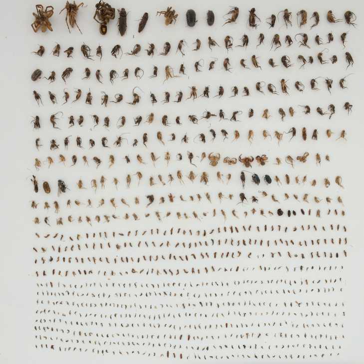
Mark off 12- by 12-inch ceramic tile so that all individuals, labels and color selector card/reference ruler will be in a rectangle 8 inches wide by 12 inches tile. These dimensions take advantage of the native 3:2 camera settings and allow higher resolution than imaging a square foot tile. Place the color selector card in the bottom right and all labels from the tube in the bottom left of the rectangle.
Sample image, downscaled from 110mb original.
Turn on all lights and set Savage LED60K to maximum. Turning on the camera should turn on Canon EOS Utility. Select "Remote Shooting" which will open a new window. Camera settings:
1. F-stop= F22
2. Shutter Speed= 1/30
3. ISO= 500
Choose "Live View Shoot." Under "Focus" choose FlexiZone= "Single" and set Continuous AF "On." Use the cursor to set the autofocus zone on the smallest organisms in the image. If you set in on a large individual, there will be a depth of field problem for the small individuals. Select the correct folder to house the image. Take image. Save image to /PROJECT/IMAGES/1_RAW/SITE/
Sample screen-cap of .CR2 raw image.
Image Processing
This section converts the raw .CR2 file into morphometric and color data as well as creating a new, smaller image for each individual.
Crop raw .CR2 photo and convert to a .tif file.
Open photo in Photoshop. If necessary, rotate from horizontal to vertical, crop so that only the tile is shown in the image. Make certain that all individuals, labels and the color selector card are visible in the image. Note that cropping the image does not change the resolution. Save this file as a .tif file using the following settings:
1. Image Compression="None"
2. Pixel Order="Interleaved"
3. Byte Order="Macintosh" (unless you are not using a mac)
4. Layer Compression: (None of the three choices should be selectable)
Convert cropped .tif file to "red" binary file. The goal of the two step color thresholding is to create a file that accurately and completely differentiates between the organism and the tile background (and is thus "binary").
1. Open cropped .tif file in FIJi
2. Select Image -> Adjust -> Color Threshold
a. Thresholding method=MaxEntropy
b. Threshold color=Red
c. Color Space=RGB
Start with the following settings:
d. Red= (0 , 255)
e. Green= (0 , 170)
f. Blue= (0 , 120)
If there are a lot of light colored organisms or parts not turning red, up the second blue value incrementally 10 units at a time. Approaching (0 , 180), shadows will start to create "fuzz" around the edges of large-bodied organisms. I reduce the blue value until these edges lose their "fuzz."
3. Save binary file as a .tif. Be sure to name the file correctly as you are about to cover up any identifying information in the image.
4. Create white boxes to cover any features or regions you do no want extracted (labels, tile edges, etc.)
a. Change the eye-dropper color to white.
b. Use the rectangle too create a box large enough to cover whatever you are hiding
c. Hit command-d to fill rectangle with white
d. Save and replace binary file
5. Separate any organisms that are touching
a. Keep the eye-dropper color to white
b. Click twice on pencil tool to set the line width to 2
c. Use the pencil to draw a line separating the touching organisms
d. Save and replace binary file
6. Fill in missing parts of organisms with red
a. Change the eye-dropper color to red. Click once on eye-dropper and then click on any red pixel in the binary image
b. Use the pencil and/or paint brush tool to color red in any parts that were not detected in the thresholding.
c. Save and replace binary file
Extract morphometric measurements and ROI file
1. Open the saved "red" /BINARY/ file in FIJI.
2. Analyze -> Set Scale.
For our methods:
a. Distance in Pixels=27
b. Known distance=1
c. Unit of length=mm
3. Analyze -> Set Measurements
a. Area
b. Bounding Rectangle
c. Shape Descriptors
d. Centroid
e. Perimeter
f. Fit Ellipse
g. Feret's Diameter
4. Select Image -> Adjust -> Color Threshold
a. Thresholding method:MaxEntropy
b. Threshold color: Black
c. Color Space: RGB
d. Red 255, 255
e. Green 0,0
f. Blue 0,0
g. We don't save the "Black" thresholded image
5. Analyze -> Analyze particles
a. Show overlay
b. Check:
i. Display results
ii. Clear Results
iii. Add to manager
c. Click "OKAY"
6. Save measurements
a. activate the "Results" window
b. Command + s
c. Save results in appropriate directory
d. Close the .csv file
7. Save the ROI file (Regions of Interest)
a. Activate the ROI manager
b. Select "More"
c. Save .roi file in appropriate directory (but don't close the ROI, see below)
Create a single image for each individual (AKA "Chopping"). Some of the images will have >1000 individuals that are numbered 1 to n in order from the top-left-most pixel in that individual. Thus it is easier to go to the file for individual i than to look for it in the .ROI map layered over the original image.
Create the file ROIchopchop.ijm and save to PROJECT/CHOPPER/ROIchopchop.ijm. Correct the path variable in line one. Save. Open this file in FIJI and then open the /2_CROPPED/ version of the image that you want to chop up. Run the script. This will save the individual images in the ~/6_CHOP/SITE/event directory you must manually create. I prefer to do this so that I can make certain the number of individuals matches the .roi file.
Before running this, I:
1. manually open the CROP image and the ROI file for that image. This helps me make certain the scale is set correctly for processing. When you restart the computer, FIJI defaults back to a different resolution.
2. create a separate directory for each image in the correct SITE directory ~/PROJECT/6_CHOP/SITE/
3. I copy and paste the event name into the script below (below "RMNP_002.20180917.IB.01.IMG_01")
ROIchopchop.ijm
path="/Users/michaelweiser/Google Drive/MacroSystems/Data/Imaging/Invertebrate_ByCatch/";
eventname="RMNP_002.20180917.IB.01.IMG_01";
imagename=eventname+".tif";
roiname=eventname+".zip";
print(eventname)
////extract site name from event name
site=substring(eventname,0,4)
selectWindow(imagename);
for (i=0; i run("Duplicate...", "title=crop");
roiManager("Select", i);
run("Crop");
///saveAs("Tiff", path+"CHOPOUTPUT/"+eventname+"."+(i+1)+".tif");
saveAs("Tiff", path + "IMAGES/6_CHOP/"+site+"/"+eventname+"/"+eventname+"."+(i+1)+".tif");
close();
print(i+1);
//Next round!
selectWindow(imagename);
}
///roiManager("delete");
///close();
print((getTime()-start)/1000);
Extract RGB Color values for each individual.
After using the chop script, I close the ROI and CROP files and then reopen them. Again, it helps me make certain that the two files are set to the same correct scale.
Create and save colorextract.ijm (code below). The "site substring" in this file looks for the four letter site code specific to NEON samples (e.g. "CPER"). Open the /2_CROPPED/ version of the image of interest
////colorextract.ijm
////6October2021
path="/Users/michaelweiser/Google Drive/MacroSystems/Data/Imaging/Invertebrate_ByCatch/";
eventname="RMNP_002.20180917.IB.01.IMG_01";
imagename=eventname+".tif";
roiname=eventname+".zip";
///filename=File.nameWithoutExtension
print(eventname)
///site=substring(getTitle(),0,4)
site=substring(eventname,0,4)
print(site)
///Open image
//open(path+"IMAGES/2_CROPPED/"+site+"/"+imagename);
///Open ROI
//open(path+"IMAGES/4_ROI/"+site+"/"+roiname);
///Split into RGB layers
run("Make Composite");
///Set metrics for extracting ROI color
run("Set Measurements...", "mean standard min integrated skewness kurtosis stack display add redirect=None decimal=3");
///Turn on ROI manager with labels
roiManager("Show All with labels");
///measure all layers
roiManager("multi-measure measure_all");
////save .csv file with name of image in file name
saveAs("Results", path+ "IMAGES/8_COLOR/"+site+"/"+eventname+".csv");
////Clear the ROI manager
roiManager("Delete");
////Close the image
close();
Databasing methods
Create loader table in MySQL
CREATE TABLE IF NOT EXISTS `PON_Loader` (
`ROI` int(11) DEFAULT NULL,
`Label` varchar(30) DEFAULT NULL,
`Area` decimal(10,3) DEFAULT NULL,
`X` decimal(10,3) DEFAULT NULL,
`Y` decimal(10,3) DEFAULT NULL,
`Perim` decimal(10,3) DEFAULT NULL,
`BX` decimal(10,3) DEFAULT NULL,
`BY` decimal(10,3) DEFAULT NULL,
`Width` decimal(10,3) DEFAULT NULL,
`Height` decimal(10,3) DEFAULT NULL,
`Major` decimal(10,3) DEFAULT NULL,
`Minor` decimal(10,3) DEFAULT NULL,
`Angle` decimal(10,3) DEFAULT NULL,
`Circ` decimal(10,3) DEFAULT NULL,
`Feret` decimal(10,3) DEFAULT NULL,
`IntDen` decimal(10,3) DEFAULT NULL,
`RawIntDen` int(11) DEFAULT NULL,
`FeretX` int(11) DEFAULT NULL,
`FeretY` int(11) DEFAULT NULL,
`FeretAngle` decimal(10,3) DEFAULT NULL,
`MinFeret` decimal(10,3) DEFAULT NULL,
`AR` decimal(10,3) DEFAULT NULL,
`Round` decimal(10,3) DEFAULT NULL,
`Solidity` decimal(10,3) DEFAULT NULL
) ENGINE=InnoDB DEFAULT CHARSET=latin1
Create Taxonomy Table
Probably not necessary for most projects, but we had to link image id's to metagenomic data from NCBI taxonomy.
CREATE TABLE IF NOT EXISTS `PON_taxa` (
`PonTaxonID` int(11) NOT NULL,
`ITIS_TSN` int(11) DEFAULT NULL,
`NCBI_TID` int(11) DEFAULT NULL,
`PON Name` varchar(100) DEFAULT NULL,
`Phylum` enum('Annelida','Arthropoda','Mollusca','Rotifera','Platyhelminthes') DEFAULT NULL,
`Subphylum` varchar(30) DEFAULT NULL,
`Class` varchar(30) DEFAULT NULL,
`Subclass` varchar(30) DEFAULT NULL,
`Superorder` varchar(30) DEFAULT NULL,
`Order` varchar(30) DEFAULT NULL,
`Suborder` varchar(30) DEFAULT NULL,
`Infraorder` varchar(30) DEFAULT NULL,
`Superfamily` varchar(30) DEFAULT NULL,
`Family` varchar(30) DEFAULT NULL,
`Subfamily` varchar(30) DEFAULT NULL,
`Genus` varchar(30) DEFAULT NULL,
`Species` varchar(30) DEFAULT NULL,
`Det_Level` varchar(30) DEFAULT NULL,
`DateLastConfirmed` timestamp NOT NULL DEFAULT CURRENT_TIMESTAMP,
`Source` varchar(30) DEFAULT NULL,
UNIQUE KEY `PON Name` (`PON Name`)
) ENGINE=InnoDB DEFAULT CHARSET=latin1;
Create occurrence table in MYSql
CREATE TABLE IF NOT EXISTS `PON_Occ_Data` (
`PON_Occ_Data_ID` int(10) unsigned NOT NULL AUTO_INCREMENT,
`ROI` int(11) DEFAULT NULL,
`Label` varchar(30) DEFAULT NULL,
`PonTaxonID` int(11) DEFAULT NULL,
`det. by` enum('MDW','MDW with Bugguide') DEFAULT NULL,
`Area` decimal(10,3) DEFAULT NULL,
`X` decimal(10,3) DEFAULT NULL,
`Y` decimal(10,3) DEFAULT NULL,
`Perim` decimal(10,3) DEFAULT NULL,
`BX` decimal(10,3) DEFAULT NULL,
`BYY` decimal(10,3) DEFAULT NULL,
`Width` decimal(10,3) DEFAULT NULL,
`Height` decimal(10,3) DEFAULT NULL,
`Major` decimal(10,3) DEFAULT NULL,
`Minor` decimal(10,3) DEFAULT NULL,
`Angle` decimal(10,3) DEFAULT NULL,
`Circ` decimal(10,3) DEFAULT NULL,
`Feret` decimal(10,3) DEFAULT NULL,
`IntDen` decimal(10,3) DEFAULT NULL,
`RawIntDen` int(11) DEFAULT NULL,
`FeretX` int(11) DEFAULT NULL,
`FeretY` int(11) DEFAULT NULL,
`FeretAngle` decimal(10,3) DEFAULT NULL,
`MinFeret` decimal(10,3) DEFAULT NULL,
`AR` decimal(10,3) DEFAULT NULL,
`Round` decimal(10,3) DEFAULT NULL,
`Solidity` decimal(10,3) DEFAULT NULL,
PRIMARY KEY (`PON_Occ_Data_ID`)
) ENGINE=InnoDB DEFAULT CHARSET=latin1;
Move data from loader to occurrence
INSERT INTO PON_Occ_Data (ROI,Label,Area,X,Y,Perim,BX,BYY,Width,Height,Angle,Circ,Feret,IntDen,RawIntDen,FeretX,FeretY,FeretAngle,MinFeret,AR,Round,Solidity)
SELECT
ROI, Label, Area, X, Y, Perim, BX, BY, Width, Height, Angle, Circ, Feret, IntDen, RawIntDen, FeretX, FeretY, FeretAngle, MinFeret, AR, Round, Solidity
FROM PON_Loader;
TRUNCATE TABLE `PON_Loader`;
Create table color_loader
CREATE TABLE IF NOT EXISTS `color_loader` (
`index` int(11) DEFAULT NULL,
`label` varchar(50) DEFAULT NULL,
`mean` decimal(6,3) DEFAULT NULL,
`stddev` decimal(6,3) DEFAULT NULL,
`min` int(11) DEFAULT NULL,
`max` int(11) DEFAULT NULL,
`intden` float DEFAULT NULL,
`skew` decimal(4,3) DEFAULT NULL,
`kurt` decimal(4,3) DEFAULT NULL,
`rawintden` int(11) DEFAULT NULL,
`channel` varchar(10) DEFAULT NULL
) ENGINE=InnoDB DEFAULT CHARSET=latin1;
DROP TABLE IF EXISTS color_cleaner;
CREATE TABLE color_cleaner SELECT * FROM color_loader;
DELETE FROM color_cleaner WHERE label="Label";
ALTER TABLE `color_cleaner` CHANGE `channel` `channel` VARCHAR( 10 ) NULL DEFAULT NULL;
UPDATE color_cleaner SET channel="red" WHERE channel="1";
UPDATE color_cleaner SET channel="green" WHERE channel="2";
UPDATE color_cleaner SET channel="blue" WHERE channel="3";
Create table color rows
CREATE TABLE IF NOT EXISTS `color_rows` (
`col_label` varchar(50) DEFAULT NULL,
`image` varchar(50) DEFAULT NULL,
`IL_Site` varchar(4) DEFAULT NULL,
`IL_Number` varchar(3) DEFAULT NULL,
`ROINumber` int(11) DEFAULT NULL,
`meanRed` decimal(6,3) DEFAULT NULL,
`stddevRed` decimal(6,3) DEFAULT NULL,
`minRed` int(3) DEFAULT NULL,
`maxRed` int(3) DEFAULT NULL,
`intDenRed` float DEFAULT NULL,
`skewRed` decimal(4,3) DEFAULT NULL,
`kurtRed` decimal(4,3) DEFAULT NULL,
`rawIntDensRed` int(11) DEFAULT NULL,
`meanGreen` float DEFAULT NULL,
`stddevGreen` float DEFAULT NULL,
`minGreen` int(3) DEFAULT NULL,
`maxGreen` int(3) DEFAULT NULL,
`intDenGreen` float DEFAULT NULL,
`skewGreen` float DEFAULT NULL,
`kurtGreen` float DEFAULT NULL,
`rawIntDensGreen` int(10) DEFAULT NULL,
`meanBlue` float DEFAULT NULL,
`stddevBlue` float DEFAULT NULL,
`minBlue` int(3) DEFAULT NULL,
`maxBlue` int(3) DEFAULT NULL,
`intDenBlue` float DEFAULT NULL,
`skewBlue` float DEFAULT NULL,
`kurtBlue` float DEFAULT NULL,
`rawIntDensBlue` int(10) DEFAULT NULL,
KEY `image` (`image`),
KEY `image_2` (`image`)
) ENGINE=InnoDB DEFAULT CHARSET=latin1;
ALTER TABLE `color_cleaner`
ADD `IL_Site` VARCHAR( 4 ) NULL DEFAULT NULL AFTER `label` ,
ADD `IL_Number` VARCHAR( 3 ) NULL DEFAULT NULL AFTER `IL_Site`,
ADD `ROINumber` VARCHAR( 4 ) NULL DEFAULT NULL AFTER `IL_Number`;
UPDATE color_cleaner SET `IL_Site`=LEFT(label,4);
UPDATE color_cleaner SET `IL_Number`=MID(label,6,3);
UPDATE color_cleaner SET ROINumber=MID(label,36,4);
SELECT * FROM color_cleaner WHERE label LIKE "%.W.201%%"
UPDATE color_cleaner SET ROINumber=MID(label,38,4) WHERE label LIKE "%.N.201%%";
UPDATE color_cleaner SET ROINumber=MID(label,38,4) WHERE label LIKE "%.S.201%%";
UPDATE color_cleaner SET ROINumber=MID(label,38,4) WHERE label LIKE "%.E.201%%";
UPDATE color_cleaner SET ROINumber=MID(label,38,4) WHERE label LIKE "%.W.201%%";
CREATE TABLE colormorph SELECT * FROM PON_Occ_Data;
ALTER TABLE `color_cleaner` ADD INDEX ( `channel` );
DROP TABLE IF EXISTS color_rows;
CREATE TABLE color_rows
SELECT label, IL_Site, IL_Number, ROINumber,
mean AS meanRed,
stddev AS stddevRed,
mini AS minRed,
maxi AS maxRed,
intden AS intDenRed,
skew AS skewRed,
kurt AS kurtRed,
rawintden AS rawIntDensRed
FROM color_cleaner
WHERE channel="Red";
ALTER TABLE `color_rows`
ADD `meanGreen` FLOAT NULL DEFAULT NULL ,
ADD `stddevGreen` FLOAT NULL DEFAULT NULL ,
ADD `minGreen` INT( 3 ) NULL DEFAULT NULL ,
ADD `maxGreen` INT( 3 ) NULL DEFAULT NULL ,
ADD `intDenGreen` FLOAT NULL DEFAULT NULL ,
ADD `skewGreen` FLOAT NULL DEFAULT NULL ,
ADD `kurtGreen` FLOAT NULL DEFAULT NULL ,
ADD `rawIntDensGreen` INT( 10 ) NULL DEFAULT NULL ;
ALTER TABLE `color_rows`
ADD `meanBlue` FLOAT NULL DEFAULT NULL ,
ADD `stddevBlue` FLOAT NULL DEFAULT NULL ,
ADD `minBlue` INT( 3 ) NULL DEFAULT NULL ,
ADD `maxBlue` INT( 3 ) NULL DEFAULT NULL ,
ADD `intDenBlue` FLOAT NULL DEFAULT NULL ,
ADD `skewBlue` FLOAT NULL DEFAULT NULL ,
ADD `kurtBlue` FLOAT NULL DEFAULT NULL ,
ADD `rawIntDensBlue` INT( 10 ) NULL DEFAULT NULL ;
ALTER TABLE `color_rows` ADD INDEX ( `IL_Site` );
ALTER TABLE `color_rows` ADD INDEX ( `IL_Number` );
ALTER TABLE `color_rows` ADD INDEX ( `ROINumber` );
ALTER TABLE `color_cleaner` ADD INDEX ( `IL_Site` );
ALTER TABLE `color_cleaner` ADD INDEX ( `IL_Number` );
ALTER TABLE `color_cleaner` ADD INDEX ( `ROINumber` );
UPDATE color_rows, color_cleaner
SET meanGreen=mean,
stddevGreen=stddev,
minGreen=mini,
maxGreen=maxi,
intDenGreen=intden,
skewGreen=skew,
kurtGreen=kurt,
rawIntDensGreen=rawintden
WHERE color_rows.IL_Site=color_cleaner.IL_Site
AND color_rows.IL_Number=color_cleaner.IL_Number
AND color_rows.ROINumber=color_cleaner.ROINumber
AND color_cleaner.channel="green";
UPDATE color_rows, color_cleaner
SET meanBlue=mean,
stddevBlue=stddev,
minBlue=mini,
maxBlue=maxi,
intDenBlue=intden,
skewBlue=skew,
kurtBlue=kurt,
rawIntDensBlue=rawintden
WHERE color_rows.IL_Site=color_cleaner.IL_Site
AND color_rows.IL_Number=color_cleaner.IL_Number
AND color_rows.ROINumber=color_cleaner.ROINumber
AND color_cleaner.channel="blue";
CREATE TABLE color_rows2 SELECT * FROM color_rows GROUP BY label;
DROP TABLE IF EXISTS color_rows;
RENAME TABLE `PON_2020_MASTER`.`color_rows2` TO `PON_2020_MASTER`.`color_rows` ;
Combine morphology and color data in MYSql
DROP TABLE IF EXISTS PONworking, A;
CREATE TABLE A
SELECT DISTINCT * FROM PON_Occ_Data;
CREATE TABLE PONworking
SELECT * FROM PON_taxa, A
WHERE PonTaxonID=PonTaxonIDT
AND PonTaxonID IS NOT NULL;
DROP TABLE IF EXISTS A;
CREATE TABLE PONTaxMorCol
SELECT * FROM PONworking,color_rows
WHERE PONworking.Label=color_rows.image
AND PONworking.ROI=color_rows.ROINumber;