Jun 21, 2018
- Moreno D'Amico1,
- Edyta Kinel2,
- Piero Roncoletta1,
- Gabriele D'Amico1
- 1SMART Lab (Skeleton Movement Analysis & Advanced Rehabilitation Technologies) Bioengineering & Biomedicine Company Srl, Pescara, Italy;
- 2Department of Rheumatology and Rehabilitation, Clinic of Rehabilitation, University of Medical Sciences, Poznan, Poland


External link: https://doi.org/10.1371/journal.pone.0203679
Protocol Citation: Moreno D'Amico, Edyta Kinel, Piero Roncoletta, Gabriele D'Amico 2018. ASAP POSTURE. protocols.io https://dx.doi.org/10.17504/protocols.io.q5zdy76
Manuscript citation:
- D’Amico M, D’Amico G, Roncoletta P. Algorithm for Estimation, Classification and Graphical Representation of Clinical Parameters in the Measurement of Scoliosis and Spinal Deformities by Means of Non-Ionising Device. Three Dimens Anal Spinal Deform. 1995;15: 33–38. doi:10.3233/978-1-60750-859-5-33
- D’Amico M, Roncoletta P. 3D Determination of spinal deformities and postural variability by Mean of Opto-electronic Device: recent algorithmic improvements. Stud Health Technol Inform. 1997;37: 155–159. doi:10.3233/978-1-60750-881-6-155
- D’Amico M, D’Amico G, Roncoletta P. A 3-D Biomechanical Skeleton Parametric Fitting Model from opto-electronic Body Landmarks Measurement for Spinal Deformities Evaluation and Posture Analysis. Proceedings of the XVIII ISB (International Society of Biomechanics) Congress. Zurich: H. Gerber R. Muller; 2001. Available: https://isbweb.org/images/conf/2001/Longabstracts/PDF/0200_0299/0205.pdf
- D’Amico M, Roncoletta P. Joint segmental kinematic trunk motion and C.O.P. patterns for multifactorial posturographic analysis. Res Spinal Deform 3. 2002;91: 149–52.
- D’Amico M, Ciarrocca F, Liscio G, Serafini P, Tommasini M, Vallasciani M. Balance lower limb loads and 3D spine modifications after total hip joint replacement: effects of leg length discrepancy correction. Res Spinal Deform 5. 2006;123: 409–14.
- D’Amico M, D’Amico G, Roncoletta P. A 3-D biomechanical skeleton model for posture and movement analysis. Res Spinal Deform 5. 2006;123: 188–194.
- D’Amico M, D’Amico G, Roncoletta P, Tomassini M, Ciarrocca F, Vallasciani M. A 3-D biomechanical skeleton model and processing procedure. Eur Med Phys. 2007;43: 1–6.
- D’Amico M, D’Amico G, Frascarello M, Paniccia M, Roncoletta P, Vallasciani M. A 3-D skeleton model & SEMG approach for integrated neck and low back pain analysis test batteries. Res Spinal Deform 6. 2008;140: 79–84.
- D’Amico M, D’Amico G, Roncoletta P, Paniccia M, Vallasciani M. Full skeleton mean gait cycle description in normal population by means of integrated multifactorial approach. Gait Posture. 2008;28: S34–S35. doi:10.1016/j.gaitpost.2007.12.063
- D’Amico M, D’Amico G, Paniccia M, Roncoletta P, Vallasciani M. An integrated procedure for spine and full skeleton multi-sensor biomechanical analysis & averaging in posture gait and cyclic movement tasks. Res Spinal Deform 7. 2010;158: 118–126.
- D’Amico M, Bellomo RG, Saggini R, Roncoletta P. A 3D spine & full skeleton model for multi-sensor biomechanical analysis in posture & gait. 2011 IEEE International Workshop on Medical Measurements and Applications Proceedings (MeMeA). 2011. pp. 605–608. doi:10.1109/MeMeA.2011.5966711
- D’Amico M, Roncoletta P, Di Felice F, Porto D, Bellomo R, Saggini R. LBP and lower limb discrepancy: 3D evaluation of postural rebalancing via underfoot wedge correction. Res Spinal Deform 8. 2012;176: 108–112. doi:10.3233/978-1-61499-067-3-146
- D’Amico M, Roncoletta P, Di Felice F, Porto D, Bellomo R, Saggini R. Leg length discrepancy in scoliotic patients. Res Spinal Deform 8. 2012;176: 146–150. doi:10.3233/978-1-61499-067-3-146
- D’Amico M, Kinel E, Roncoletta P. Normative 3D opto-electronic stereo-photogrammetric posture and spine morphology data in young healthy adult population. PLOS ONE. 2017;12: e0179619. doi:10.1371/journal.pone.0179619 https://journals.plos.org/plosone/article?
- D’Amico M, Kinel E, D’Amico G, Roncoletta P. A 3D Spine and Full Skeleton Model for Opto-Electronic Stereo- Photogrammetric Multi-Sensor Biomechanical Analysis in Posture and Gait. 2017; doi:10.5772/intechopen.68633
- D’Amico M, Kinel E, Roncoletta P. 3D quantitative evaluation of spine proprioceptive perception/motor control through instinctive self-correction maneuver in healthy young subjects’ posture: an observational study. Eur J Phys Rehabil Med. 2018; doi:10.23736/S1973-9087.17.04738-4
- Kinel E, D’Amico M, Roncoletta P (2018) Normative 3D opto-electronic stereo-photogrammetric sagittal alignment parameters in a young healthy adult population. PLOS ONE 13(9): e0203679. https://doi.org/10.1371/journal.pone.0203679 https://journals.plos.org/plosone/article?>
License: This is an open access protocol distributed under the terms of the Creative Commons Attribution License, which permits unrestricted use, distribution, and reproduction in any medium, provided the original author and source are credited
Protocol status: Working
We use this protocol and it's working
Created: June 20, 2018
Last Modified: June 21, 2018
Protocol Integer ID: 13209
Keywords: Stereo-photogrammetry, 3D Posture, 3D Spine, 3D Full Skeleton Reconstruction, 3D Non-ionising Evaluation, Posturography, Stabilometry, full skeleton 3d posture measurement, 3d parametric biomechanical skeleton model, analyse human posture, posture, spine marker, human posture, electronic stereophotogrammetric measurements of body landmark, spinal stiffness, several accurate anthropometric measurement, body landmarks visibility during rotation, body landmark, erect standing posture, scoliosis, full 3d multilevel posturography, detailed description of lower limb, spine process, following anatomical landmark, anatomical landmark, subject in erect standing posture, anterior aspect of body, right zygomatic bone, s3 every second vertebra c7, second vertebra c7, anthropometric data, remaining body landmarks visibility, back pain, posterior superior iliac spine, dimensions of each skeleton, related anthropometric data, electronic stereophotogrammetric measurement, skeleton, posterior aspect of body, different body la
Abstract
A non-ionising approach based on 3D opto-electronic stereophotogrammetric measurements of body landmarks labelled by passive retro-reflective markers has been chosen to build a 3D parametric biomechanical skeleton model. The developed model can work at different stages of complexity. That is, depending on different analysis purposes and necessities, the parametric scaling can be detailed with several accurate anthropometric measurements, and the dimensions of each skeleton’s component are estimated and fitted to match the subject’s skeleton. To this aim, various protocols involving different body labelling (and so different related anthropometric data) have been established for separate analyses.
A 27 markers protocol has been set to analyse human posture and spinal associated pathologies (scoliosis, back pain etc.), and tested extensively in the clinical environment. With such a protocol some functional evaluation can be successively performed like Full 3D Multilevel Posturography/Stabilometry and/or Side Bendings to study spinal stiffness/mobility.
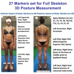
27 Markers set for Full Skeleton 3D Posture Measurement
The following anatomical landmarks are identified:
Anterior Aspect of Body: Markers (n=8)
Left and Right Zygomatic bones,
Mentum (Chin at mental protuberance),
Left and Right Sterno-Clavicular Joint,
Sternum at Xyphoid prominence,
Left and Right ASIS (ASIS=Anterior Superior Iliac Spine)
Posterior Aspect of Body: Markers (n=19)
Spine Markers (n=11): from C7 down to S3 every second vertebra C7, T2, T4, T6, T8, T10, T12, L2, L4, S1, S3 (on the tip of spinous processes)
Left and Right Acromion
Left and Right PSIS (PSIS=Posterior Superior Iliac Spine)
Left Knee and Right Knee (back of the knee at the middle point of the popliteal fossa)
Left and Right Heel (lateral process of calcaneal tuberosity)
When a more detailed description of lower limb segmental poses is sought, for instance when gait trials have to be considered, the used number of markers is to be increased.
The actual 27 Marker Protocol, chosen to build a 3D parametric biomechanical skeleton model, is part of a general methodology which can be applied indifferently to any stereo-photogrammetric recording system, provided that the latter is able to supply all the required landmarks three-dimensional coordinates, with known stereophotogrammetric error (after system calibration) in order to consider error magnification during the processing/elaboration chain.
Recommendation
Hemispheric retro-reflective passive markers have to be adopted in order to minimise the bone-prominence/marker distance and reduce geometrical interferences.
The sizes of the adopted retro-reflective passive markers can vary depending on the size of the subject that undergoes to examination.
For subjects in the age range starting from adolescence through adulthood up to elderly the suggested marker size to adopt on the spine processes and on the Posterior Superior Iliac Spines (PSIS) of the pelvis is 10mm diameter. Conversely, 15mm diameter marker size can be used to maximise the remaining body landmarks visibility during rotations.
For children, the suggested marker size to adopt is smaller (down to 6mm) depending on the size and age of the child under examination.
Marker positioning has to be performed, by palpation, by a skilled, trained operator, with the subject in erect standing posture.
Guidelines
Generalizability
The actual 27 Marker Protocol, chosen to build a 3D parametric biomechanical skeleton model, is part of a general methodology which can be applied indifferently to any stereo-photogrammetric recording system, provided that the latter is able to supply all the required landmarks three-dimensional coordinates, with known stereophotogrammetric error (after system calibration), in order to consider error magnification during the processing/elaboration chain.
Recommendation
Hemispheric retro-reflective passive markers have to be adopted in order to minimise the bone-prominence/marker distance and reduce geometrical interferences.
The sizes of the adopted retro-reflective passive markers can vary depending on the size of the subject that undergoes to examination.
For subjects in the age range starting from adolescence through adulthood up to elderly the suggested marker size to adopt on the spine processes and on the Posterior Superior Iliac Spines (PSIS) of the pelvis is 10mm diameter. Conversely, 15mm diameter marker size can be used to maximise the remaining body landmarks visibility during rotations.
For children, the suggested marker size to adopt is smaller (down to 6mm) depending on the size and age of the child under examination.
When a more detailed description of lower limb segmental poses is sought, for instance when gait trials have to be considered, the used number of markers is to be increased.
Subject preparation
The subject is asked to undress and to stay in underwear (underpants and bra for female) and/or swimming suit (bikini like for female) in order to allow a proper marker positioning through all the necessary body landmarks, with particular attention to having the full accessibility to the spinous processes of the spine. For such a reason subjects with long hair are asked to comb their hair to leave the neck free at least at C5 level. If possible it is better men be shaved in order to avoid difficulties in placing markers on the face.
Marker Placement
Markers positioning has to be performed, by palpation, by a skilled, trained operator, with the subject in erect standing posture, using a nonallergenic double-sided adhesive tape.
In the placement of the markers on the spinous processes of the spine, it is suggested to start identifying C7 and S3 levels first. The spinous process of C7 should be localized by palpation of the two most prominent cervical spinal processes during flexion and the assisted extension of the cervical spine.C7 is the spinous process remained stationary during this manoeuvre. S3 is identified by palpating the area located at the beginning of the inter-gluteal groove. After identifying these first two spinous processes, proceed with palpation to identify the remaining spinous processes one every two vertebrae.
Subject Positioning
When the assessment/measurement session is aimed to fully capture and record the subject’s neutral unconstrained erect-standing posture, the subject is asked to align heels on a line parallel to the frontal plane and to keep feet apart (without restricting feet directions) at about pelvis width (i.e. with feet under the projection of the hip joints), with the upper arms relaxed along the side of the body, eyes looking directly ahead in the horizontal plane and mouth closed.
Acquisition Protocol
The static postural attitude is considered to be accurately recorded when at least five acquisitions, each of two seconds duration, are captured and successively averaged. The number of the 3D measurement to be averaged can vary depending on the chosen opto-electronic stereophotogrammetric device data acquisition rate.
Troubleshooting
Safety warnings
We strongly recommend using a nonallergenic double-sided adhesive tape.
It is important to have a constant monitoring of the subject during all the period of the postural evaluation session including Marker Positioning procedure, to prevent and promptly avoid any possible lipothymy/fainting crisis (very rare but possible).
Before start
In order to reduce potential postural effects resulting from circadian rhythms, and perform appropriate postural comparisons, the moment of the day in which the measurement is performed should be carefully annotated.
The subjects are asked to avoid any intensive training and/or hard physical activity before the postural assessment.
A face-to-face interview and a thorough clinical postural examination before each session of postural measurement are strongly suggested to gather full necessary information about the actual functional/clinical status of each subject.