May 13, 2026
Acute Neuropixels Recording Through a 3D Printed Implant
- Yoni Browning1,
- Galen Lynch1,
- Camille King1,
- Anna Lakunina1,
- Meghan Olsen1,
- Xinxin Yin1,
- Josh Siegle1
- 1Allen Institute / Neural Dynamics
- Allen Institute for Neural Dynamics


Protocol Citation: Yoni Browning, Galen Lynch, Camille King, Anna Lakunina, Meghan Olsen, Xinxin Yin, Josh Siegle 2026. Acute Neuropixels Recording Through a 3D Printed Implant. protocols.io https://dx.doi.org/10.17504/protocols.io.261ge3zwyl47/v1
License: This is an open access protocol distributed under the terms of the Creative Commons Attribution License, which permits unrestricted use, distribution, and reproduction in any medium, provided the original author and source are credited
Protocol status: Working
We use this protocol and it's working
Created: May 05, 2023
Last Modified: May 13, 2026
Protocol Integer ID: 81478
Keywords: Neuropixels, Acute recordings, Systems neuroscience, Extracellular electrophysiology, acute neuropixels recording, extracellular electrophysiology recording, neuropixels probe, density extracellular electrophysiology recording, neuropixel, other instruments in the brain region, such as neuropixel, density electrode array, shield craniotomy, spiking activity, brain region, living brain, brains at an unprecedented scale, brain, clamp, head bar
Abstract
High-density electrode arrays, such as Neuropixels, make it possible to record spiking activity from living brains at an unprecedented scale. Here we describe a protocol for high-density extracellular electrophysiology recordings using a SHIELD craniotomy to provide brain-wide access, a head bar and clamp that precisely locates the brain in our recording setup, and a modular insertion system to flexibly position Neuropixels probes and other instruments in the brain regions being studied.
Materials
Vybrant™ DiI Cell-Labeling SolutionThermo Fisher ScientificCatalog #V22885
MilliQ water
Propylene Glycol Eye Drop (Systane)Alcon in a 3:1 (Sorta-a-clear:Systane) ratio by weight prior to the degassing step. Note that sort-a-clear mixes better if made in relatively large quantities, e.g. 50 g at a time. However, since Systane only comes in small tubes it is better to aliquot out a small (e.g. 3 g) amount of sort-a-clear to make each batch.
Tergazyme Solution:
Mix Terg-a-zyme® enzyme detergentMerck MilliporeSigma (Sigma-Aldrich)Catalog #Z742918-1.8KG with deionized or reverse osmosis water at 1 Mass Percent ratio, (e.g. 0.1 g Tergazyme with 10 mL water). Stir, shake, or vortex until dissolved. Premixed Tergazyme has a shelf life of 1 week, after which it should be replaced. Store covered and labeled, noting that it is "Not for Animal Use."
Ethanol 70%
Stick Vacuum (Brand agnostic, but should have HEPA filter).
Software
Open Ephys GUI
NAME
Open Ephys
DEVELOPER
REPOSITORY
SOURCE LINK
x
Software
Pinpoint
NAME
Dan Birman, Kenneth Yang
DEVELOPER
SOURCE LINK
Equipment
Neuropixels
NAME
1.0, 2.0, Ultra, Opto
TYPE
IMEC
BRAND
Equipment
Modular Insertion System (MIS)
NAME
New Scale
BRAND
LINK
Safety warnings
DOWSIL-2025 is toxic and corrosive. It must be disposed of properly (consult your EHS or equivalent), including a dedicated hazardous waste stream in an appropriate container (consult the MSDS). It will also degrade the plastic wells typically used for water, dye, etc. If possible, a dedicated well made from a non-reactive substrate (e.g. Titanium) for probe dipping is advisable.
Ethics statement
Research-focused rodent behavior must be conducted according to internationally accepted standards and should always have prior approval from an Institutional Animal Care and Use Committee (IACUC) or equivalent ethics committee(s).
This protocol has been approved by the Allen Institute Animal Care and Use Committee (IACUC).
PHS Assurance: D16-00781
AAALAC: Unit 1854
Before start
Prior to performing this protocol, the mouse must have been properly prepared with head-fixing and a 3D printed implant compatible with the recording rig.
Prepare the Rig for Recording
1h 16m
Understand rig axes and rotation conventions.
We use a Modular Insertion System that can be purchased from New Scale Technologies or fabricated from open-source designs. The insertion system consists of a set of arcs that form a dome centered around a point inside the mouse brain. Arc sliders move laterally along each arc and hold interchangeable modules for Neuropixels probes, stick microscopes, lasers, and optical fibers. Each Neuropixels module includes a 3-axis micromanipulator with 15 mm of travel along each axis, which is used to align the probe with the target and insert it into the brain. A vertical translation stage (Zaber stage) moves the arcs out of the way when inserting and removing the mouse.
Key components of the Modular Insertion System
The rig coordinate system is centered around the approximate location of bregma for each mouse.
Each location is described by three coordinates:
1. ML (medial/lateral) coordinate, with positive values toward the mouse's right
2. AP (anterior/posterior) coordinate, with positive values toward the mouse's anterior
3. SI (superior/inferior) coordinate, with positive values above the mouse
The default orientation of a probe in this coordinate system is for shank 0 (left-most shank in a multi-shank probe) to be at the origin, and the electrodes to be facing the left of the mouse.
Global coordinate system used to describe positions and rotations of probes during the experiment.
Rotations of the inner arcs along the outer arc are positive when they move in the posterior direction and negative when they move in the anterior direction.
Rotation conventions for the outer arcs. Note that the mouse's head (and therefore the insertion coordinate system) is tilted at an angle of –14º.
Rotations of the arc sliders along an inner arc are positive when they move toward the mouse's right and negative when they move toward the mouse's left.
Rotation conventions for the inner arcs.
Rotations of the probe around the insertion axis are positive when the probe is moved in the counter-clockwise direction and negative when the probe in moved in the clockwise direction.
Aligning a probe's local coordinate system with the rig's global coordinate system.
Therefore, the orientation of the probe is fully described by three angles:
1. Arc angle (positive posterior, with 0º pointing in the direction of the global SI axis)
2. Arc slider angle (positive right, with 0º pointing in the direction of the global SI axis)
3. Local rotation (positive counter-clockwise, with the electrodes facing mouse left at 0º)
Configure New Scale software for micromanipulator control.
When moving probes, we use the Xbox controller interface for New Scale MPM. Below is our preferred button mapping:
Here is one key binding for a Xbox controller. Some users prefer to switch the X and Y buttons. Here, the X button locks out the Y axis (allows X movement).
Configure probe module angles by adjusting the arcs and arc sliders.
The precise angles will depend on the number of probes the desired target regions for each probe. In cases where implant holes have high positional variability, appropriate rig angles might also vary by mouse.
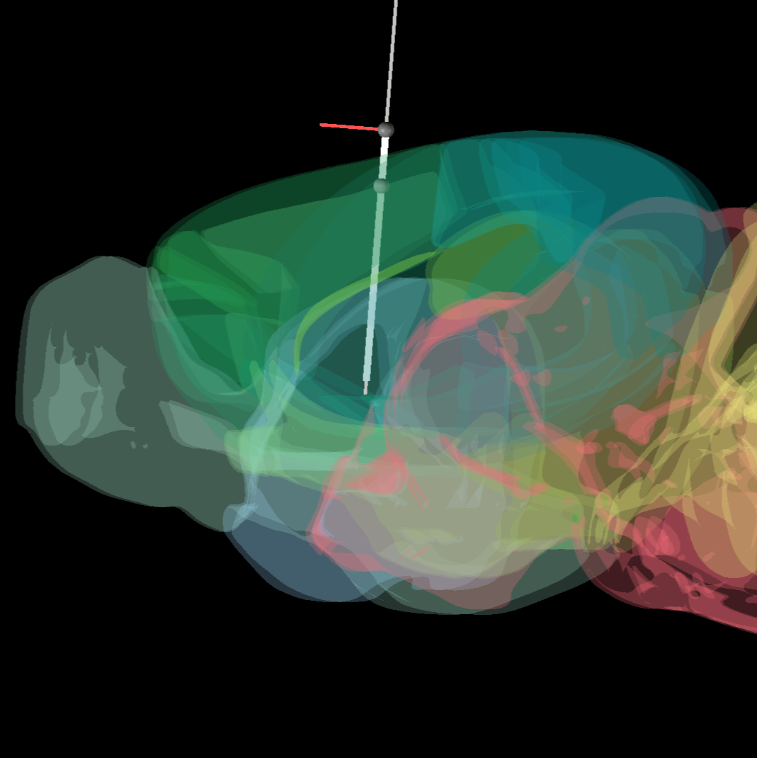
If not using MRI to guide insertions, Pinpoint provides an excellent web-based tool for experimental planning.
A screenshot of Pinpoint software.
1h
Prior to adjusting the position of arcs or arc sliders, fully retract probes along the Z axis to avoid collisions:
- Ensure that all probes are fully retracted to 0 um in the Z axis using New Scale MPM control software.
- Unbolt each probe from its respective arc slider by unscrewing the center bolt (A) with an Allen key. If properly unscrewed, the bolt should be free to pull up through its unthreaded portion.
- Ensure that each manipulator is at at least ~7500 um in the Y axis before attempting to manually raise a probe. This will ensure that the manipulator has clearance to safely move away from the arc/arc slider.
- Using the two silver plunger rings on the side of each probe (C), pull outwards to release the plunger mechanism and slide each probe up to its retracted position. Both springs should release at the top to secure the probe in place over the two silver rods on each side of the probe holder. Tighten the black thumb screw (B) on the side of each probe for extra security.
Relevant components of a probe attached to an arc slider.
To adjust arc (A/P) position:
- To adjust the angle of an arc, turn the black handles on either side of the arc in opposite directions to loosen/tighten. Each black handle can be pulled outwards while turning to provide more space for making angle adjustments.
- If adjusting many probes, it is often useful to temporarily position A/P angle of each arc to allow maximum space for rearranging individual probes and arc sliders.
A/P adjustments can be made without unplugging probes. However, before moving probes in M/L or between arc sliders, they must be unplugged to prevent strain on the cables:
- Unplug the Omnetics connector on the probe headstage.
- Unplug the probe ground wires.
- Unplug the USB cable on the New Scale controller, then its power cable. This order is the safest way to prevent power issues with the controllers.
- Safely position the cables so that they will not damage probes.
To adjust arc slider (M/L) position on an arc:
- Loosen the four bolts holding the slider in position (D).
- Adjust the position of the slider using the tick marks on the arc.
- Tighten the four bolts back into place. Optimally, use a star pattern (e.g. top left, bottom right, top right, bottom left) to limit twist.
Moving a slider between arcs follows similar logic:
- Undo the four holding the slider in position. They are "captured" so will not fall out of the module when the back plate is free. Keep hold of both the front and back components of the arc slider when unscrewing.
- Move the slider to the new location on the new arc and tighten the four bolts back into place.
To move a probe to a different module:
- Loosen the black thumbscrew and pull both silver rings outwards to carefully remove the entire probe from its arc slider.
- IMPORTANT: Keep an eye on the probe shank to avoid collisions while removing. Temporarily place your probe in a safe location.
- Position the receiving slider and carefully return the module to the new slider.
Once your probe(s) are in place:
- Thread all three cables along the top of the arc. Ensure that you have sufficient slack to accommodate the movement of the Zaber stage.
- Plug in the cables (probe Omnetics connector, probe ground, New Scale controller). Plug in the New Scale power first, then USB to prevent overdrawing USB power.
- If you retracted any probes for movement, the plungers will hold the probe in its retracted position. To lower to operating height, pull back the silver plunger rings and gently lower down. Use the New Scale MPM software to adjust probe locations if there is a risk of contact during this process.
- Once all probes are in their working position, tighten the center bolt on the module.
Typically, it is best to move A/P arcs away from each other for optimal access to M/L sliders. You can then position each arc slider at its intended M/L angle. Once M/L angles are set, the final A/P positions can be applied. This order prevents access issues from having the arcs too close together.
Once everything is in place, plug in any probes that were unplugged during rig setup. Cables can be reorganized along the top of each arc at this point.
Check and/or adjust the spin angle of each probe using its probe dial. If there is not a dial attached, approximate its spin compared to with a probe with a known spin (see the diagram above). If you are removing probes from the rig, this step can also be done more easily while they are not bolted down.
For recordings using multishank Neuropixels probes, it can be useful to note which direction the electrode sites are facing when adjusting a probe’s spin. Our typical convention assumes that when a probe has a spin of 0 degrees, electrode sites are facing left relative to the mouse.
Open New Scale MPM and reorder your probes in a way that makes sense for your insertion plan. Click “setup connection” to reorder your selected ports or to select available ports, and then click “connect.” Our probe order in the New Scale software typically goes from front to back and left to right when looking at the front of the rig (i.e. facing the mouse's face).
Screenshot of New Scale MPM control software.
Position stick microscopes such that they have good visibility of experimental working space, without impeding probe movement. You may need to adjust the arc slider positions to achieve this.
While the manually determined angles provide a reasonable estimate of probe orientation, more precise localization can be achieved by measuring the transformation from probe to rig space. The resulting transformation matrices can then be used to determine the exact location of the probe tip relative to the rig's global coordinate system.
Calibrating the probe can be done manually. Alternatively, Parallax, a software package (Neural Dynamics - Development) provides an automated alternative for probe calibration.
Apply fluorescent dye to the probes.
Before dipping the probes in dye, we recommend placing each probe in the approximate X/Y location that will be used during the experiment. That way, when lowering the probes into the dye, you can confirm that there will be no collisions prior to insertion.
Dyes are typically chosen based on their desired fluorescent and histological properties. CM-DiI is preferred if no other constraints exist (e.g. interference with other fluorescence signals). Multiple dyes can be used on separate probes in a given an experiment; in this case, repeat the following for each dye:
- Place the well corresponding to the chosen dye in the rig. Fill with dye using a transfer pipette.
- Lower the Zaber stage to the height used during recording (see "Insert Probes" step for more details).
- Dip probes into dye. Each probe should be submerged at least as far as they will be inserted into the brain. Repeat dipping 5-6 times, waiting ~15 seconds between dips.
Note
Why do we dip more than once?
We have not done a parametric comparison relating number of dips to strength of probe track in histology. However, qualitative comparisons suggest that the histology from experiments with 1-3 dips show weaker probe tracks than histology from experiments with 5-6 dips. One proposed explanation for this is that each dip builds a small layer of dye on the probe, so that each dip deposits more dye on the probe.
In any case, it is also worth noting that dye diffuses in the brain over time, so weak probe tracks can become untraceable in histology after ~2 weeks.
If dipping is not providing sufficient probe tracks in your histology, one viable option is to "paint" your probe. Here, use a micropipette to measure a droplet of 1-2 uL dye, then carefully rub this droplet onto the probe (you should be able to use surface tension on the droplet to determine that you are making contact). This will deposit much more dye onto the probe and lead to brighter probe tracks in histology, but we consider this too dangerous to use when there are many probes in close proximity due to the risk of breakage.
- Retract probes and raise the Zaber stage.
- Remove the well from the rig, and use a transfer pipette to place unused dye back into storage container for future use.
Note
Because dyes are both light and temperature sensitive, it is best to do this step as close as possible to the actual recording.
15m
Launch your electrophysiology acquisition software, such as the Open Ephys GUI, and ensure that all probes are detected. Double check that the desired electrode configuration and reference settings are selected for each probe.
1m
Prepare Mouse for Recording
5m
Place mouse on rig.
(a) Tighten the headframe clamp in the following order to ensure that the mouse is positioned correctly and repeatably:
- Hand tighten the front screw (A).
- Use an Allen key to tighten the side screw (B).
- Use the Allen key to finish tightening the front screw (A).
(b) An optional stabilizing bolt can be used to further clamp the headframe in place. It is typically not necessary for Neuropixels recordings (it was designed for optical techniques).
This figure demonstrates the basic headframe clamping setup. Note that specific headframe used may vary (e.g. whole hemisphere craniotomy headframes look different than the one shown above), but the clamping procedure remains the same.
This figure is from A standardized head-fixation system for performing large-scale, in vivo physiological recordings in mice - PubMed (nih.gov), which contains detailed information about the headframe and clamp design.
Example mouse with headframe clamped and well cap in place.
Remove well cap. Position probe guard so that ground pin makes contact with the corresponding pin in the mouse's well.
Example mouse with well cap removed and pin (A) visible.
Mouse with tail guard attached.
Ensure that the mouse is properly grounded to the rig via its tail guard.
The tail guard contains a gold pin that mates with a gold pin on the headframe well. The surfaces of these pins should be flush and should maintain good electrical contact throughout the experiment.
On the mouse side, the gold pin is soldered to a silver wire that gently rests against the brain surface underneath the layer of Duragel. The voltage level at the brain surface is considered the "animal ground."
On the rig side, the gold pin is soldered to a wire that is routed to a grounding harness. The following rig components must be connected to the harness via low-impedance metal wires (e.g. banana cables):
1. Mouse platform (via headframe clamp)
2. GND and REF of all Neuropixels probes
3. Capacitive lick detectors
All components connected to the grounding harness should be electrically isolated from the rest of the rig. For example, the mouse platform should be isolated from the air table it is mounted on, either via ceramic posts or metal posts insulated with non-conductive tape.
The image below shows the recommended grounding configuration:
Grounding configuration for acute Neuropixels recording.
Note
When Neuropixels probes are set to "tip" reference mode, the filtered and common-average-referenced signal can appear clean even if the probe ground is disconnected from the animal ground. However, this only works if all electrodes are inside the brain. Seeing a clear signal change when the probe enters the brain (and therefore precisely determining the location of the surface) requires that the probe ground be electrically conductive with the brain. Being able to view low-noise raw signals also makes it easier to identify sources of noise in the recording and remove them without the need for post-processing.
Insert Probes
40m
Lower Zaber stage into place using Zaber stage software controller.
Rough positioning can be done manually, but the final movement should use the Zaber command line interface to ensure minimal error in stage position. Because there are two Zaber stages (one for each side of the rig), we use lockstep commands to move both axes at the same time. We store the set position for recording as position "1".
The Zaber command to move to this position is:
/lockstep 1 move stored 1
Note
The first time you configure a rig, you will need to set up these positions and lockstep groups. Consult the Zaber manual for more information.
Screenshot of Zaber stage software controller.
Insert the first probe into the brain.
Position the probe in X and Y so it's aligned with its target hole. If an MRI volume is available, the X and Y positions can be determined based on the known location of the target point inside the brain. If no MRI is available, the probe should be manually aligned with the center of its target hole while visualizing its motion with two or more microscope modules.
If the Duragel surface is difficult to see using the stick microscopes (for example, if it becomes dirty), consider adding a small amount of saline or ACSF to the bottom of the well to help with visibility.
Once the probe is aligned in X and Y, it can be driven down along the Z axis using the New Scale MPM control software. The initial approach can be carried out with the motion set to "coarse" speed, but once the probe is in the Duragel the speed should be switched to "fine."
Before the probe enters the brain, make sure its data stream is visible in your acquisition software (e.g. Open Ephys GUI). The most reliable way to tell when the probe contacts the brain surface is to monitor its signals in real time. When the tip of the probe leaves the Duragel and comes into contact with the brain, there should be a sharp voltage deflection. After that, spikes will appear on the first few channels to enter the brain.
If the probe bends before entering the brain, it likely indicates that membrane regrowth has made it more difficult to penetrate. Driving the probe forward and backwards along the Z axis can sometimes help it push through. If this doesn't succeed, consider pulling the probe out of the Duragel and moving it slightly before penetrating again. In some cases, probes may need to be left out of the recording if they are unable to penetrate into the brain.
Once the probe reaches the surface, zero its coordinates in the New Scale software so its precise depth will be visible throughout the insertion process.
In the New Scale software, switch the probe's manipulator to "insertion" mode. With speed no greater than 200 um/min, drive the probe to the desired depth.
Note
For the first ~10 seconds of this insertion, it is important to continuously monitor the probe. In the event that the probe has not entered the brain, it may begin to visibly bend during the early part of this insertion process. If this happens, back off the Z axis and try again to penetrate the brain.
Repeat the previous step for all probes to be used in the recording. Driving each probe to depth can be slow. If you are inserting multiple probes, subsequent insertions can take place while the initial probes are moved into place.
Once all probes are at depth, wait at least 00:05:00 (for deeper insertions or longer recordings, up to 10 min) for the brain to settle around the probe.
5m
Perform Recordings
2h 20m
Press the record button in the Open Ephys GUI (or similar acquisition software) to start recording. Alternatively, recording can be triggered remotely (e.g., via the Open Ephys GUI's built-in HTTP server).
Any behavioral task or stimulation protocol should begin after the ephys recording has been started.
Important: Be sure you have a way to synchronize recorded Neuropixels probes with your behavior control system. See the Open Ephys GUI documentation for more information.
After the recording is complete, carry out a surface finding procedure.
If all of the active electrodes for a given probe were inside the brain, the precise location of the brain surface cannot be extracted from your recording. For example, if a single-shank Neuropixels 2.0 probe is inserted more than 2.8 mm, when the deepest 384 electrodes are selected there will be no contacts spanning the brain surface.
In the Open Ephys GUI, sites spanning the surface can be detected using "Survey Mode." The Survey Mode interface is accessible via a tab in the visualizer for the Neuropix-PXI or OneBox plugins. You can configure Survey Mode to automatically scan subset of each probe's banks/shanks for a set period of time. We typically opt for a setup that records from each bank of electrodes that was not active during the original recording. Be sure the "Record survey to disk" option is selected so the data is saved.
"Survey Mode" interface in the Open Ephys GUI.
Record at least00:02:00 min of data in each alternate configuration. See the Open Ephys GUI documentation for more information.
10m
Retract Probes and Remove Mouse
5m
Retract probes from the brain using the New Scale software, with control speed set to "fine."
Once all probes are retracted, raise Zaber stage to a sufficient height to allow the mouse to be easily removed from the rig.
Place a cap over the mouse's well and return it to its cage.
Clean the Rig
52m
Use a vacuum with a HEPA filter to remove mouse feces/debris from the rig.
2m
Wipe all surfaces contacted by the mouse with ethanol to disinfect the rig prior to the next recording.
Clean probes with Tergazyme
- Place a dedicated Tergazyme well in the rig and fill with a transfer pipette.
- Lower the Zaber stage to the height used during the recording.
- Drive all probes into Tergazyme. Probes should be submerged at least as far as they were inserted into the brain. Soak for at least 00:30:00 or up to Overnight .
- Retract probes from Tergazyme and raise the Zaber stage.
- Remove well and rinse with deionized water to prevent Tergazyme residue from building up.
30m
Remove Tergazyme by dipping probes in deionized (DI) water
- Place the water well in the rig and fill with deionized water using a transfer pipette.
- Lower the Zaber stage to the height used during the recording.
- Drive all probes into the water. Probes should be submerged at least as far as they were inserted into the Tergazyme. Dip several times, or soak for 00:15:00 to Overnight .
- Retract probes from water and raise the Zaber stage.
- Remove well and discard excess water.
15m
Remove dye from probes (if using a different dye for the next insertion)
- Dyes are alcohol soluble. Place a dedicated alcohol well in the rig and fill with ethanol or isopropanol using a transfer pipette.
- Lower the Zaber stage to the height used during the recording.
- Drive all probes into alcohol, making sure to dip them at least as far as the dye extends up the probe. A few seconds of submersion should be sufficient.
- Retract probes from alcohol and raise the Zaber stage.
- Remove well and discard excess alcohol.
5m
Optional: Clean Duragel from probes
After several uses, Duragel residue can coat the probes, leading to a drop in signal quality. If you suspect that Duragel buildup is affecting your recordings, or if you see visible residue on the probe when viewed through a microscope, the probe should be cleaned with DOWSILdef-2025.
Safety information
DOWSIL-2025 is toxic and corrosive. It must be disposed of in a dedicated hazardous waste stream in an appropriate container (consult your Environment, Health, and Safety team and the Material Safety Data Sheet for more information). It will also degrade the plastic wells typically used for water, dye, etc. If possible, use a dedicated well made from a non-reactive substrate (e.g. titanium).
- Place a dedicated well in the rig and fill with DOWSIL-2025 using a transfer pipette.
- Lower the Zaber stage to the height used during the recording.
- Drive all probes into the solvent. Probes can be left in the solvent overnight with no risk of damage, but you can typically see residue dissolve immediately.
- Retract probes from solvent and raise the Zaber stage.
- Remove well and dispose of solvent in the appropriate waste stream.
- Clean the remaining DOWSIL-2025 from the probes by dipping them first in water, then in alcohol (see two previous steps of this protocol).
Protocol references
Birman, Daniel, et al. "Pinpoint: trajectory planning for multi-probe
electrophysiology and injections in an interactive web-based 3D
environment." bioRxiv (2023).
Groblewski PA, Sullivan D, Lecoq J, de Vries
SEJ, Caldejon S, L'Heureux Q, Keenan T, Roll K, Slaughterback C,
Williford A, Farrell C. A standardized head-fixation system for
performing large-scale, in vivo physiological recordings in mice. J
Neurosci Methods. 2020 Dec 1;346:108922. doi:
10.1016/j.jneumeth.2020.108922. Epub 2020 Sep 15. PMID: 32946912.
Siegle JH, Cuevas López A, Patel YA, Abramov K, Ohayon S, Voigts J
(2017) Open Ephys: an open-source, plugin-based platform for
multichannel electrophysiology. J Neural Eng 14: 045003