May 21, 2025
A robust open source photogrammetry workflow for digitizing macroscopic specimens
This protocol is a draft, published without a DOI.
- Mario Schädel1
- 1University of Tübingen


Protocol Citation: Mario Schädel 2025. A robust open source photogrammetry workflow for digitizing macroscopic specimens. protocols.io https://dx.doi.org/
License: This is an open access protocol distributed under the terms of the Creative Commons Attribution License, which permits unrestricted use, distribution, and reproduction in any medium, provided the original author and source are credited
Protocol status: Working
We use this protocol and it's working
Created: May 18, 2025
Last Modified: May 21, 2025
Protocol Integer ID: 218498
Keywords: photogrammetry, Structure from Motion, SfM, point cloud, surface model, surface scanning, robust open source photogrammetry workflow, photogrammetric workflow, based surface capture, accurate 3d surface data, surface capture, 3d surface models of the studied object, 3d surface model, digitizing macroscopic, imaging equipment, scale surface model, imaging process, proper photographic equipment, contemporary morphometric analysis, photography, surface, palaeoanthropoogy lab, teaching at the palaeoanthropoogy lab, background of the object, studied object, more pointcloud, active illumination, computed tomography, digital model, accuracy of the digital model, imaging, specimen
Disclaimer
The author does not guarantee the accuracy of your models. In theory, this workflow should provide similar accuracy as commercial surface scanners. If you are in doubt about the accuracy of your mesh, compare measurements recorded from the mesh with measurements recorded from the physical specimen or test your mesh against one derived from another source of shape information (e.g. CT data).
Abstract
Most contemporary morphometric analyses rely on 3D surface models of the studied objects. They can stem from computed tomography (e.g. x-ray CT), active illumination or stereo-photography-based surface capture or photogrammetry. All of these methods have the potential to create accurate, to-scale surface models, if used correctly. Photogrammetry allows to capture surfaces without big investments in imaging equipment – although proper photographic equipment can aid the imaging process.
The goal of this protocol is to enable the reader to capture accurate 3D surface data through a photogrammetric workflow that involves a thorough examination of the intermediate data to ensure the sanity and accuracy of the digital model. The workflow includes two well established, freely available, open source programs: COLMAP and Cloud Compare. One of the key points of the workflow is that objects can be captured from all sides without masking the background of the objects by stitching two or more pointclouds. This workflow has been developed for teaching at the Palaeoanthropoogy lab at the University of Tübingen.
Guidelines
You can follow this workflow step by step, but please feel free to adapt it to your needs. COLMAP offers a plethora of settings and parameters that can be optimized for your imaging needs.
Materials
Hardware
The following list refers to the components used to test this workflow and might not represent the ideal setup (not a purchasing recommendation).
- Nikon D7200 (APS-C sensor) DSLR camera
- Nikon micro Nikkor 60 mm AF macro lens
- Nissin MF-18 ring flash (two independent segments)
- self-crafted automated turntable
From available lenses the Nikon micro Nikkor 60 mm AF macro lens was chosen because it is a fixed-focal length lens (less distortion than a zoom lens) and it has a relatively wide field of view compared to other macro lenses with e.g. 100 mm focal length. A ring flash was chosen as it proved important to light the specimen independent from the rooms lighting and in a way that there is not much shadowing at the object turntable contact surface.
The turntable is controlled by a Raspberry Pi Pico micro controller (programmed using micro Python). The turntable movement is accomplished with a cheap stepper motor. The rotating platform was cut-out from Medium-density fibreboard (MDF). The connection to the stepper motor was 3D printed – as was the three platform guiding pillars (necessary due to the poor quality of the stepper motor). The motor, controller and other electronic parts are housed in a wooden box. The turntable is programmed to rotate in discrete steps, making pauses for image capture (no connection to camera).
The rotating platform is equipped with a sheet of paper with multiple 100 mm scale bars and an irregular high contrast pattern (for the SIFT feature extraction to pick up).
A simpler setup could be to use a smart phone camera (focal length is fix) and either move around the specimen or rotate the specimen on a cardboard that lies on a desk. A sufficient illumination could be accomplished by indirect light from windows.
Software
- COLMAP, open source (BSD license), available on Linux and Windows, available at https://colmap.github.io, Nvidia graphics card and CUDA drivers required for dense reconstruction, building from source code recommended on Linux
- CloudCompare, open source (GPL v.2 license), available on Linux, Windows and MacOS, available at https://www.danielgm.net/cc/
Safety warnings
The author of this workflow has no professional background in computer vision and photogrammetry in particular. Please consult the appropriate research literature and cite the relevant publications suggested by the developers of the software used herein. The author is also not involved in the development of the software tools used in the protocol and should therefore not be credited as such.
When working with museum material, consult the curator regarding your rights on the captured images and respect (and criticize if necessary) the museums policies for specimen access and imaging.
Do not delete your captured images unless you are perfectly fine with the final model and explicitly wish to not attempt an improved reconstruction in the future.
Ethics statement
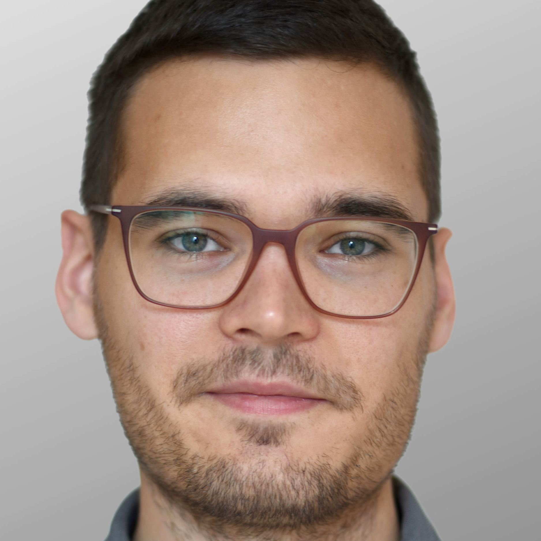
The data used herein (a cast of a Neanderthal talus) should not pose ethical concerns. However, your to-digitize objects might be more problematic. This is entirely your or your supervisor's responsibility.
Before start
This workflow can be separated in three main parts: Imaging, Structure from Motion and point cloud cleaning. Creating a mesh is the final step in this workflow.
Photography
Set the camera capture mode and/or the parameters for manual capture. This should include setting a small aperture (high f number), as the entire object and some space around it should be in focus. Make sure to adjust the other settings, such that this does not result in a long exposure time if you don't use a tripod (a flash will also eliminate the problem).
Adjust the flash settings and other camera settings to ensure that the captured images are appropriately lit, well exposed and free of motion blur.
One of the images used for this demonstration.
Use the turntable to rotate the specimen in discrete steps that ensure enough but not excessive overlap between the images. In this example, I used 12 steps for a full rotation and images in two orbits around each of the two sides of the specimen. Your object and camera setup may require a different camera positioning and possibly more steps per full rotation. To be cautious, you can also add another image (in this example a 13th) to ensure a proper loop closure in the sparse reconstruction (not necessary).
In the camera, check the completeness of your captured image series and whether the flash fired properly in all images.
Turn the specimen on its other side and repeat the image capture.
Organizing files
Download the files from the camera's memory card and transfer them to the computer. Put them on a fast SSD drive if possible.
Organize the photos like in the depicted directory structure.
Structure from Motion using COLMAP
Open the COLMAP GUI.
Go to File and New project.
Create a database file (.db) in your workspace directory and specify the directory with the images. This will let COLMAP know where to look for your images.
Then click Save and close this window.
Click on Reconstruction and then on Automatic reconstruction. The following window will then pop up.
Specify the workspace folder, i.e. the folder which COLMAP will use to store the results and intermediate files. For this choose side_1 following the above naming scheme.
Specify the folder with the images (inside of the workspace folder). Yes, this is a bit redundant, as you just specified it for the database file.
Set the Quality to Low or Medium (everything else will take much longer to process).
Tick the boxes for Shared intrinsics (only do this is if you used a fixed focal length camera!)
Tick the boxes for Sparse model and Dense model. The former should be selected by default and the latter will ensure that COLMAP will, without intervention, perform the dense reconstruction (can be started manually otherwise).
Leave everything else at the default values.
Click Run and wait. This can and will take some time (within the range of a few minutes).
COLMAP will display you the result of the sparse recontruction (!) in the main window. At this point you should check the inferred camera positions. The camera symbols are likely too high and the points too small. You can change the rendering options by clicking on Render and then select Render options.
You will find your reconstruction results in the workspace folder you specified before. The interesting files for the further analyses are in the folder dense and therein in the folder 0. The file fused.ply contains the dense point cloud.
Inspect the dense point cloud in a 3D viewer of your choice (e.g. Meshlab). The most important thing to check here is that the platform on which the physical specimen was placed is reconstructed as a flat plane. This tells you that there is no major problem with the overall geometry of your scan. Also check whether there are any larger gaps in your model which the scan of the other side will not be able to fill.
If the scan looks fine with you, you can proceed to the next section.
It may be that the dense reconstruction is a bit noisy in the sense that there are points "attached to the real surface" and that these points are of a different color than the surface of your object. In this case it might help to adjust a parameter of the fusion process (dense reconstruction).
In COLMAP go to Reconstruction and then Dense reconstruction. A new window will appear, where you have to specify the Workspace directory by clicking on Select.
The directory you want to select here is the 0 folder within the dense folder. This way, COLMAP has access to all previously computed intermediate files and you don't have to do undistort the images again and compute stereo depth maps and normal maps.
When you see images listed here, click on Options, which will open another window with parameters to set. There move to the Fusion tab and change min_num_pixels from 5 (default) to something higher, say 10.
Close the Dense reconstruction options window.
Make sure to rename the result of your previous dense reconstruction (fused.ply), so that your comparison file will not be overwritten. E.g. call it fused_default.ply
In the Dense reconstruction window click on Fusion and wait for the dense reconstruction to finish.
Your new dense reconstruction will overwrite the old fused.ply file and will now also be displayed in the main COLMAP window.
Point cloud alignment in CloudCompare
Open CloudCompare and drag both point clouds onto the main window. Just click apply both times (using the default import settings).
Hide one of the sides by removing the tick on the top-left pane and select the point cloud object of the other.
If you have trouble seeing the points properly, increase the Point size in the point cloud properties (point cloud needs to be selected).
Use the measurement tool to measure the length of the scale bars.
For this, set it to the 2 point mode (second from left) and select the two end points on the scale bar.
There may appear a dialog window asking you to agree to calculate an octree object. You can agree to this.
Note that the endpoints of your measurements will always be located on points of the point cloud.
Take note of your measurement, repeat the measurement for another scale bar and average the two or more values. I will refer to this value as d in the following.
Calculate the scaling factor
In my case the scaling factor is 72.31.
Scale the point cloud by exiting the measurement mode and, with your point cloud selected, go to Edit and then to Apply transform. Then switch to the Tab Axis, Angle and set your scaling factor. This works for the older program versions. In the newer, there is a separate menu Multiply/Scale for this (one entry below).
If you then unhide the other point cloud, you'll see it is much smaller than the point cloud you just upscaled. You can now re-measure the scale bar to ensure the correct scale.
Scale the other point cloud as well (don't reuse the scaling factor!). After that your models should be of the same scale.
This is a good point to save your progress. Select both entries and go to File and Save. It will save what you have selected as a binary file (.bin extension), which can be opened again in CloudCompare if you made a mistake.
Now, we can remove the platform points. Select of of the point clouds and hide the other.
Click the scissors icon to start segmenting the unwanted points. If you want to move the model, click the pause icon.
Use the left and right mouse buttons to place the corners of your selection polygon.
Then click Segment out. You can also select your specimen and click Segment In.
Do this also for all obvious outlier points.
When you are finished, click on the confirmation icon.
Your removed points will re-appear but as a separate object, which you can delete.
Repeat for the other side. If you unhide the other side, you should see something like this.
Now manually align the two models.
The left mouse button rotates the model, the right mouse button translates it. With the space bare you can pause the model movements and rotate and translate the view.
When your are fine with the rough alignment, click the confirmation icon.
Align the point clouds using the ICP method. Select both clouds and go to Tools, Registration and then Fine registration (ICP).
For our purposes, it does not matter which model moves (if there are only two sides). Specify the desired Final Overlap to be relatively small (e.g. 20%, a rough guess). Not specifying this will unlikely lead to a proper alignment! Leave adjust scale unticked.
Merge the two point clouds. Select both and go to Edit and Merge. Say yes in the original cloud index dialog window.
You can revert the coloring of the points to be your photo-based RGB values.
Clean the point cloud using the SOR Filter. This will remove the remaining outliers.
I found 1 as the Standard deviation multiplier to be to harsh (looses too many good points).
Select the cleaned point cloud and go to Plugins and PoissonRecon.
I found an octree depth of 8 to be fine. Lower values will result in a lower number of mesh vertices. If the octree depth is too high, you will receive an empty mesh resolution.
Tick output density as SF to be able to display how many point cloud points contributed to the mesh locally (false color mesh, can be switched back to RGB).
As the mesh color can be distracting for quality assessment, you can change the mesh color to None.
Here, is a comparison between octree depths 8 (left) and 9 (right). For this specific type of model and imaging workflow, 8 seems to be the better choice.
Export the mesh model by selecting the desired mesh with the desired color information (usually RGB) and go to File Save. Change the format to your desired mesh file format, e.g. PLY.
Binary files are more storage efficient and should load faster but can not be properly opened in a text editor.
Your exported file should now open in any program that supports the mesh format.
Model opened in Meshlab
Model opened in Meshlab 3D Slicer
Congratulations, you digitized one specimen. You can now continue with the next.
Protocol references
Schönberger, J. L. & Frahm, J. (2016). Structure-from-Motion Revisited. Conference on Computer Vision and Pattern Recognition (CVPR).
Schönberger, J. L., Zheng, E., Pollefeys, M., & Frahm, J. (2016). Pixelwise View Selection for Unstructured Multi-View Stereo. European Conference on Computer Vision (ECCV).
Schönberger, J. L., Price, T., Sattler, T., Frahm, J. & Pollefeys, M.(2016). A Vote-and-Verify Strategy for Fast Spatial Verification in Image Retrieval. Asian Conference on Computer Vision (ACCV).
Acknowledgements
I would like to thank Katerina Harvati, Hannes Rathmann and Johanna König (all University of Tübingen) for access to the museum specimens used to develop this workflow.