Feb 11, 2026
Version 1
3D Scanning of Archaeological Teeth Using Polycam and MeshLab. V.1
- Claire Zikidi1,
- Anna Nasiakou2
- 1M. H. Wiener Laboratory for Archaeological Science, American School of Classical Studies at Athens and National and Kapodistrian University of Athens, Department of History and Archaeology;
- 2Independent Researcher
- CZikidi


Protocol Citation: Claire Zikidi, Anna Nasiakou 2026. 3D Scanning of Archaeological Teeth Using Polycam and MeshLab.. protocols.io https://dx.doi.org/10.17504/protocols.io.36wgq1ezyvk5/v1
License: This is an open access protocol distributed under the terms of the Creative Commons Attribution License, which permits unrestricted use, distribution, and reproduction in any medium, provided the original author and source are credited
Protocol status: In development
We are still developing and optimizing this protocol
Created: February 10, 2026
Last Modified: February 11, 2026
Protocol Integer ID: 242966
Keywords: 3D scanning, teeth, 3D printing preparation, osteoarchaeology, 3d scanning of archaeological teeth using polycam, archaeological teeth using polycam, resolution dental scanning without specialised laboratory equipment, dimensional digitisation of archaeological skeletal remain, dental scanning, accurate surface capture, 3d scanning, archaeological skeletal remain, accurate 3d model, 3d model, photogrammetry, resolution scanning, detailed surface geometry, polycam, such digitisation, fidelity 3d model, textures of skeletal element, dslr camera, meshlab, dimensional digitisation, handling of fragile specimen, based scanner, digital archiving, tool, modern smartphone, bioarchaeological research, fragile specimen
Abstract
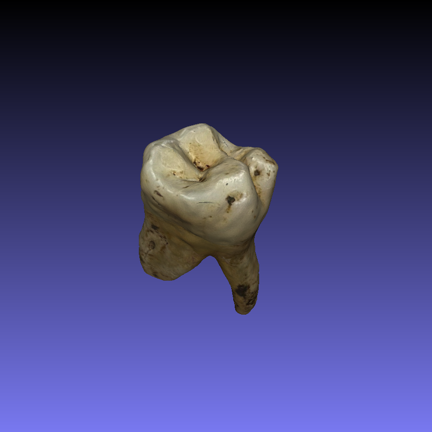
Three-dimensional digitisation of archaeological skeletal remains has become increasingly important in bioarchaeological research, providing a reliable means to document skeletal elements and preserve their structural and morphological characteristics, prior to destructive sampling. High-fidelity 3D models enable detailed virtual analysis, comparative studies, and long-term digital archiving, reducing the need for repeated handling of fragile specimens. Traditionally, such digitisation relied on high-cost laboratory-based scanners or structured light systems, which are often inaccessible in field settings or in projects with limited budget. However, recent advances in mobile technology and photogrammetry offer more cost-effective and portable alternatives, allowing high-resolution scanning using widely available devices. For example, modern smartphones, in combination with specialised applications like Polycam, can capture detailed surface geometry and textures of skeletal elements. These tools enable researchers to generate accurate 3D models quickly and efficiently, making them suitable for both field documentation and subsequent analysis. The aim of this method was to develop a reproducible, low cost workflow for digitising teeth using a DSLR camera or a mobile phone with a multi-lens camera, Polycam, and MeshLab. The methodology emphasises accurate surface capture, post-processing to correct mesh imperfections, and validation of dimensional accuracy, demonstrating the feasibility of cost-effective, high-resolution dental scanning without specialised laboratory equipment.
Materials
1. Digital camera (DSLR) with lens at least 55mm or mobile phone equipped with a multi-lens camera system to capture fine surface details and colour textures.
2. Polycam (v.5.2.3-5.2.4) – Mobile (iOS and Android) and web application for scanning and photogrammetry, enabling real-time mesh generation and texture mapping.
3. MeshLab (v2023.12) – Open-source software for mesh cleaning, scaling, hole filling, texture correction, and export.
4. LED Lighting Panels – Adjustable light sources to reduce shadows and enhance surface detail visibility.
5. Stable Surface – Maintains teeth in a fixed position during scanning.
6. Tripod or Hand Stabiliser – Ensures consistent scanning angles and minimises motion blurs.
7. Digital Calipers – For reference measurements to verify dimensional accuracy of scanned models.
Sample Preparation
1m 30s
Each tooth was mounted on a non-reflective holder or placed on flattened white adhesive putty to stabilise it during scanning.
30s
The background was set to white to avoid interferences.
30s
White LED lighting was arranged directly above the object to minimise shadows, particularly over occlusal pits and fissures, as well as roots, which are prone to missing data.
30s
3D Scanning Procedure Using Polycam
20m
Polycam was launched in normal mode, optimised for capturing small objects with high detail.
30s
When applicable (not available in android but present in iOS and web version) the object mode photogrammetry and the macro mode/flower symbol (only in iOS) were selected. The object mode is a specialised function for photogrammetry of small objects, allowing direct generation of high-quality 3D models ensuring detailed texture and geometry.
30s
Each tooth was scanned individually, maintaining a distance of approximately 5–6 cm between the lens and the tooth.
10m
The tooth was positioned on top of a white flat surface and placed under direct white light. To enhance surface capture, the operator held the device at a slight acute angle of 60–70° relative to the tooth and moved it slowly around each tooth (or use turntable) to capture multiple perspectives.
Overlapping passes -at least 75% among each image with the next- were performed to allow registering/capturing of the surfaces continuity, avoid blurry aspects ensure complete coverage of undercuts, grooves, and fissures.
To ensure capture of the entire surface (including the superior) and the texture, including polishing and small antemortem or postmortem changes, during scanning were performed periodically captures from a closer distance (4-5 cm) and / or from a more acute angle 50-60°. Additional close-up photos of detailed or intricate surfaces should be taken to improve the quality of the capture.
While moving the device to take these close-up captures the tooth was stable (it was not moved around) and the whole tooth was always capturing in all photos taken. When applicable (DSLR, iOS version), the focusing option was also optimised.
To capture also the inferior surface (roots), during scanning and after all sides of the tooth (buccal, lingual, mesial, distal) had been captured at least once, the tooth was rotated incrementally on the same side it was last captured to maintain continuity, ensuring approximately 75% overlap between the last image of one side and the first image of the next side. Scanning of all surfaces repeated as previously described also on the turned tooth.
The last image of the scan should be taken from approximately 7-8 cm from the object. In total 200–500 captures were taken for each tooth during approximately 10 minutes.
After completing photographing, the operator selected Raw Data processing, as well as Object Masking/ Isolate Object from Environment (the phrasing varies by version) and finally uploaded and processed the scan.
7m
The preliminary meshes were reviewed within Polycam, and any missing or incomplete regions were rescanned immediately and photographs were added to ensure full surface reconstruction.
1m
Completed scans were exported directly in OBJ format preserving geometry and texture for post-processing in MeshLab. OBJ was chosen for its compatibility with CAD and 3D analysis software.
1m
If needed, the scan can be remeshed with better quality results by: Remesh → Texture Resolution at 8k, Uniform Topology, Polygon Count at 100%.
Mesh Processing in MeshLab
10m
Post-processing of the scanned OBJ files was performed using MeshLab to correct mesh imperfections, ensure accurate scaling, and standardize orientation.
Each OBJ file was imported into MeshLab and inspected for common mesh artifacts, including:
- Holes in occlusal pits or between cusps
- Non-manifold edges or stray vertices
- Misalignment or scaling discrepancies relative to physical measurements
These initial inspections guided subsequent cleaning and reconstruction steps.
30s
Accurate dimensional scaling was performed to match physical measurements obtained with digital calipers. Crown height, mesiodistal width, and buccolingual width were measured on each tooth.
2m
In MeshLab, scaling was applied using the following procedure: Navigate to Filters → Normals, Curvatures and Orientations → Transform: Scale and Normalize.
30s
In the X, Y, and Z axis fields, enter the scaling factor (same for all axes) calculated as:
Scaling Factor =Measurement from calipers/ Corresponding Measurement in Meshlab.
Ensure both values used in the calculation were in the same measurement units.
30s
Apply the transformation to rescale the mesh.
30s
Retake measurements in MeshLab to verify that the model now matches the physical dimensions.
Only one reference measurement was sufficient to rescale the object accurately.
1m
Remove Duplicate Vertices:
Navigate to Filters → Cleaning and Repairing → Remove Duplicated Vertices.
This removes overlapping vertices created during scanning.
30s
Remove Isolated Components:
Go to Filters → Cleaning and Repairing → Remove Isolated Pieces (wrt Face Num) and select Remove unreferenced vertices.
Settings: Min Components Size: 100 faces (start here; if small anatomical features are removed, reduce to 50).
Apply the filter, then inspect the mesh to ensure no cusps or ridges were deleted.
This step eliminates stray vertices or floating triangles not connected to the tooth.
1m
Small gaps, especially in occlusal pits or fissures and roots, were corrected using MeshLab’s reconstruction tools:Close Holes:
Navigate to Filters → Remeshing, Simplification and Reconstruction → Close Holes.
Max Hole Size: 50–100 faces (targets small gaps without altering significant anatomical features).
Apply and inspect.
1m
Manual Repair for Larger Gaps:
For gaps that “Close Holes” cannot fix, use: Filters → Cleaning and Repairing → Merge Close Vertices (small adjustments to reconnect tiny floating edges/ Threshold: 0.01–0.05 mm).
Remove Non-Manifold Edges: After merging close vertices, meshes were inspected for topological errors such as non-manifold edges or stray geometry. These were corrected using Filters → Cleaning and Repairing → Remove Non Manifold Edges, ensuring a clean mesh suitable for measurement, visualization, and downstream analysis.
1m
Conservative Smoothing: Minor surface noise was reduced using Filters → Smoothing, Fairing and Deformation → Laplacian Smooth. Smoothing was applied with 1–2 iterations and a smoothing factor of 0.3, sufficient to remove small irregularities while preserving critical anatomical details such as cusps, fissures, and occlusal pits. Meshes were visually inspected after each iteration to confirm that morphological features remained intact.
1m
Processed tooth meshes were exported as OBJ files, retaining geometry and texture. Metadata, including scaling factors, alignment adjustments, and reconstruction steps, were documented for reproducibility.
30s
Acknowledgements
We would like to thank the Malcolm H. Wiener Laboratory for Archaeological Science and Dr. Dimitris
Michailidis for their support in providing a working space and equipment to undertake this analysis.